Basic Circuit
Hardware circuit ultrasonic range finder
Published:2014/3/6 20:53:00 Author:lynne | Keyword: Hardware circuit ultrasonic range finder, | From:SeekIC


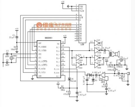
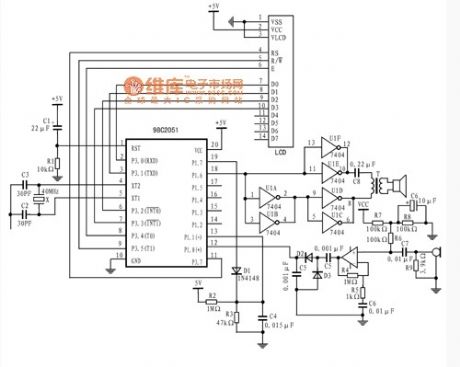
AT89C2051 by external pin P1.6 output pulse width is 250μs, the carrier is 10 pulses of 40kHz pulse group, added to the push-pull transformer primary form by upconverting promote emitted ultrasonic transducer. Simultaneously transmitted, P1.7 outputs a high level starts to charge the capacitor C4. The transmitting end toggles LOW HIGH divider C4 starts R2, R3, and the composition discharged to the negative output terminal of the comparator. Ultrasonic receiving transducer converts the received ultrasonic waves reflected by an obstacle to the amplifier for amplification, which is a high gain, low noise amplifier, the positive input of the detection signal will be amplified to detect the echo of the comparator end. The emission level of the output P1.7 can suppress the comparator flip, it can be suppressed so that the transmitter transmits the ultrasonic wave radiated to the error detection result of the receiver.
Reprinted Url Of This Article:
http://www.seekic.com/circuit_diagram/Basic_Circuit/Hardware_circuit_ultrasonic_range_finder.html
Print this Page | Comments | Reading(3)

Article Categories
power supply circuit
Amplifier Circuit
Basic Circuit
LED and Light Circuit
Sensor Circuit
Signal Processing
Electrical Equipment Circuit
Control Circuit
Remote Control Circuit
A/D-D/A Converter Circuit
Audio Circuit
Measuring and Test Circuit
Communication Circuit
Computer-Related Circuit
555 Circuit
Automotive Circuit
Repairing Circuit
Code: