Basic Circuit
HOLD_CURRENT_LIMITER
Published:2009/7/10 2:12:00 Author:May | From:SeekIC

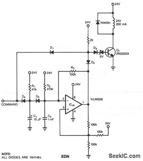
In many applications, a solenoid driver must ftrst briefly supply a large amount of pull-in current, which quickly actuates the solenoid. Thereafter, the driver must supply a much lower holding current to avoid burning the solenoid out. To avoid using the customary, cumbersome, large capacitors or power-wasting resistors, you can use the switch technique.As long as the input to the circuit is low, diode D1 holds Q1 off; a low input also prevents the op-amp circuit from oscillating. When the input reaches 24 V, Q1 switches on and pulls in the solenoid. Concurrently, D4 is back-biased, and C1 begins charging up. When C1 charges up, the op-amp circuit begins to oscillate, switching Q1 on and off.The time constant defmed by R1 and C1 determines the length of the period during which the solenoid receives full power. R3 and C2 set the oscillator's frequency, and R2 sets the oscillator's duty cycle. The hold current is directly proportional to the duty cycle. For the components shown, the full-power period is 300 ms, the oscillator's frequency is 3 kHz, and its duty cycle is 50%.
Reprinted Url Of This Article:
http://www.seekic.com/circuit_diagram/Basic_Circuit/HOLD_CURRENT_LIMITER.html
Print this Page | Comments | Reading(3)

Article Categories
power supply circuit
Amplifier Circuit
Basic Circuit
LED and Light Circuit
Sensor Circuit
Signal Processing
Electrical Equipment Circuit
Control Circuit
Remote Control Circuit
A/D-D/A Converter Circuit
Audio Circuit
Measuring and Test Circuit
Communication Circuit
Computer-Related Circuit
555 Circuit
Automotive Circuit
Repairing Circuit
Code: