Basic Circuit
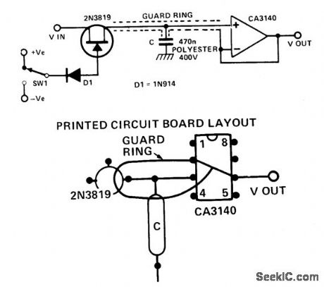
HIGH_PERFORMANCE_SAMPLE_AND_HOLD
Published:2009/7/6 5:36:00 Author:May | From:SeekIC

Circuit Notes
When switch SW1 is positive, the FET is turned on, and has a resistance of about 400 ohm. The input voltage charges up the capacitor through the FET. When SW1 is negative, the FET is turned off (pinched off). To get a long storage time, the op amp mus, have a very low input bias current. For the CA3140, this current is about 10 pico amps. The rate at which the capacitor will be discharged by this current is based on the equation, C (dv/dt)=i where dv/dt is the rate of change of voltage on the capacitor.Therefore:
Reprinted Url Of This Article:
http://www.seekic.com/circuit_diagram/Basic_Circuit/HIGH_PERFORMANCE_SAMPLE_AND_HOLD.html
Print this Page | Comments | Reading(3)

Article Categories
power supply circuit
Amplifier Circuit
Basic Circuit
LED and Light Circuit
Sensor Circuit
Signal Processing
Electrical Equipment Circuit
Control Circuit
Remote Control Circuit
A/D-D/A Converter Circuit
Audio Circuit
Measuring and Test Circuit
Communication Circuit
Computer-Related Circuit
555 Circuit
Automotive Circuit
Repairing Circuit
Code: