Basic Circuit
Greenhouse Heater Temperature Control
Published:2013/10/14 19:59:00 Author:lynne | Keyword: Greenhouse Heater Temperature Control | From:SeekIC

Standard resistance heaters used for space heaters sometimes have thermostats, but these are not adjustable to the low temperature settings required for winter greens. Instead of purchasing a high end programmable temperature controller, I fabricated this greenhouse heater temperature control project circuit. It cycles an electric heater. It has been operating for two winters now with good results, and I just added the LEDs so I could tell from a distance if it was functioning.
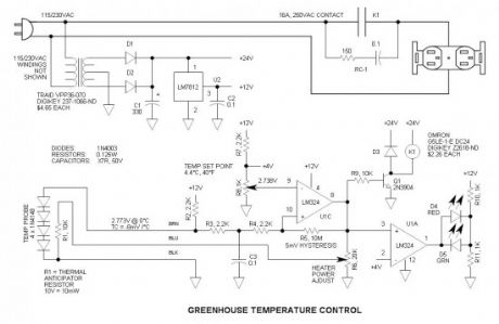
Temperature Control Circuit Schematic
Key components are documented on the schematic – there is no bill of materials.
Power supply
Basic transformer isolated full-wave center-tapped configuration with LM7812 voltage regulator
Temperature probe
This is simply (4) 1N4148 diodes connected in series with a thermal anticipation resistor (R1) heat shrunk together at the end of a (3) wire signal cable—it is visible on some of the photos. The use of a thermal anticipation resistor is an old HVAC thermostat technique that adds negative feedback to the system by immediately heating the temperature sensing device slightly. It forces short cycles and prevents temperature overshoot. Because the amount of power to apply to the thermal anticipation resistor was unknown, I incorporated a power level pot (R6).
I later determined that it works quite well at the maximum setting, so the pot is not required. Although the temperature measurement can be accomplished via a single diode, four diodes in series are used to get the signal “out of the mud.” The inexpensive LM324 op amp has a maximum input offset voltage of 7mV, so the higher level voltage signal helps to improve performance. The diodes are biased at approx 4mA via R2.
Comparator
U1C is connected as a voltage comparator with positive feedback via R5. Positive feedback prevents relay chatter. C3 is an input noise filter capacitor. As the temperature cools, the voltage drop across the probe diodes increases. When it reaches the set point, the output changes states and the positive feedback through R5 further increases the non-inverting input by 5mV to assure that it remains latched until the temperature increases and the voltage drops below the set point.
Calibration
In a previous circuit http://www.electroschematics.com/409/diode-electronic-thermometer/ we see that the temperature coefficient of silicon diodes is approx. -2mV /°C. (4) in series boosts it to -8mV /°C.
I dropped the probe in ice water and measured the voltage—2.773V in my case. Then I calculated what the voltage would be at 4.4°C (40°F). Then I adjusted the voltage at the calibration pot R8 to get 2.738V—this is the set point. Proper operation was subsequently determined by placing the probe in and out of ice water to observe cycling of the relay.
Relay driver
Q1 is a simple NPN relay driver. For more information check out this post: http://www.electroschematics.com/7123/relay-driver-2/Quencharc RC-1 is connected across the relay contacts to reduce arcing. These are unreasonably expensive, so I recommend using a discrete resistor and capacitor. Polypropylene is the capacitor of choice—just make sure that it has sufficient AC voltage rating;
LED Driver
U1A is another comparator that drives the LEDs. Red indicates power ON and Green indicates OFF.
Greenhouse specifications
For a guide for estimating your power requirements, compare your greenhouse with the following:
Dimensions: 8ft wide x 12ft long x 7ft high.
North side is insulated by high density foam to minimize heat loss
East and West ends have a double layer of plastic sheeting
South side and top are single layer greenhouse plastic—UV resistant—long life
Latitude is 40oN.
Reprinted Url Of This Article:
http://www.seekic.com/circuit_diagram/Basic_Circuit/Greenhouse_Heater_Temperature_Control.html
Print this Page | Comments | Reading(3)

Article Categories
power supply circuit
Amplifier Circuit
Basic Circuit
LED and Light Circuit
Sensor Circuit
Signal Processing
Electrical Equipment Circuit
Control Circuit
Remote Control Circuit
A/D-D/A Converter Circuit
Audio Circuit
Measuring and Test Circuit
Communication Circuit
Computer-Related Circuit
555 Circuit
Automotive Circuit
Repairing Circuit
Code: