Basic Circuit
General Wireless Alarm Launch and Receiving Circuit
Published:2011/6/15 6:57:00 Author:Michel | Keyword: General Wireless Alarm, Launch, Receiving, Circuit | From:SeekIC


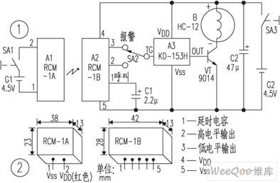
The circuit is showed as the picture and the transmitter is composed of wireless remote control launch module,A1 and battery G1 and the power switch SA1. Receiving alarm consists of wirless remote control receiving module,A2 andsimulated sound integrated circuit A3 etc.
Usually,A1 module built-in antenna launches out into the surrounding space about 250 ~ 300 MHz frequency modulation electromagnetic wave.Within effective distance,the wave is received by tiny receiving antenna inside A2 module.The wave outputs low PWL after its modulatation,amplification,test ,delay and PWL change.A3 does not work because TG PIN's low PWL, acoustic device B has no voice.Once the receiving and launching distance exceeds 15mA2 will be not able to receive enough strong transmitting signal and then A2 low pin changes into high PWL,which tirggers inside circuit work of A3.
Reprinted Url Of This Article:
http://www.seekic.com/circuit_diagram/Basic_Circuit/General_Wireless_Alarm_Launch_and_Receiving_Circuit.html
Print this Page | Comments | Reading(3)

Article Categories
power supply circuit
Amplifier Circuit
Basic Circuit
LED and Light Circuit
Sensor Circuit
Signal Processing
Electrical Equipment Circuit
Control Circuit
Remote Control Circuit
A/D-D/A Converter Circuit
Audio Circuit
Measuring and Test Circuit
Communication Circuit
Computer-Related Circuit
555 Circuit
Automotive Circuit
Repairing Circuit
Code: