Basic Circuit
GLOW_PLUG_DRIVER
Published:2009/7/2 4:56:00 Author:May | From:SeekIC

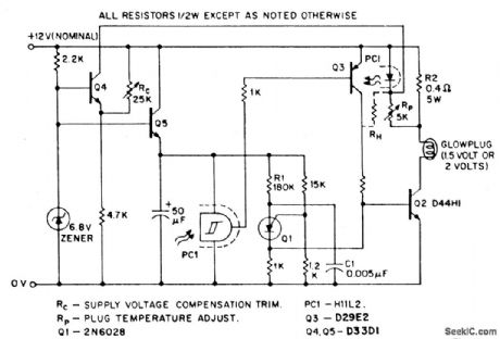
Model airplanes, boats, and cars use glow plug ignitions for their miniature (0,8cc to 15cc) internal combustion engines. Such engines dispense with the heavy on-board batteries, H.T. coil, and condenser required for conventional spark ignition, while simultaneously developing much higher RPM (hence power) than the compression ignition (diesel) motors. The heart of a glow plug is a platinum alloy coil heated to incandescence for engine starting by an external battery, either 1.5 volts or 2 volts. Supplementing this battery, a second 12-volt power supply is frequently required for the engine starter, together with a third 6 volt type for the electrical fuel pump.Rather than being burdened by all these multiple energy sources, the model builder would prefer to carry (and buy) a single 12-volt battery, deriving the lower voltages from this by use of suitable electronic step-down transformers (choppers). The glow driver illustrated does this and offers the additional benefit of (through negative feedback) maintaining constant plug temperature independent of engine flooding, or battery voltage while the starter is cranking.In this circuit, the PUT relaxation oscillator Q1 turns on the output chopper transistor Q2 at a fixed repetition rate determined by R1 and C1. Current then flows through the glow plug and the parallel combination of the current sense resistor R2 and the LED associated with the H11L Schmitt trigger. With the plug cold (low resistance), current is high, the H11L is biased on , and Q3 conducts to sustain base drive to Q2. Once the plug has attained optimum operating temperature, which can be monitored by its ohmic resistance, the H11L is programmed (viaRP).to switch off, removing base drive from Q3 and Q2.However, since the H11L senses glow plug current, not resistance, this is only valid if supply voltage is constant, which is not always the case. Transistor Q4 provides suitable compensation in this case; if battery voltage falls (during cold cranking, for instance), the collector current of Q4 rises, causing additional current to flow through the LED, thus delaying the switch-off point for a given plug current. The circuit holds plug temperature relatively constant, with the plug either completely dry or thoroughly wet , over an input voltage range of 8 to 16 volts. A similar configuration can be employed to maintain constant temperature for a full size truck diesel glow plug (28-volts supply, 12-volts glow plug); in this case, since plug temperature excursions are not so great, a hysteresis expansion resistor RH may be required.
Reprinted Url Of This Article:
http://www.seekic.com/circuit_diagram/Basic_Circuit/GLOW_PLUG_DRIVER.html
Print this Page | Comments | Reading(3)

Article Categories
power supply circuit
Amplifier Circuit
Basic Circuit
LED and Light Circuit
Sensor Circuit
Signal Processing
Electrical Equipment Circuit
Control Circuit
Remote Control Circuit
A/D-D/A Converter Circuit
Audio Circuit
Measuring and Test Circuit
Communication Circuit
Computer-Related Circuit
555 Circuit
Automotive Circuit
Repairing Circuit
Code: