Basic Circuit
GLITCH_FREE_TURBO_CIRCUIT
Published:2009/7/6 5:36:00 Author:May | From:SeekIC

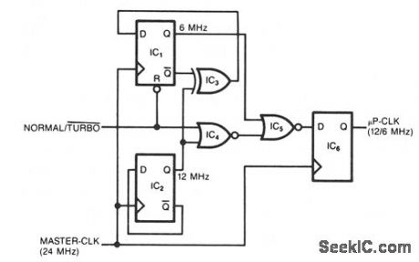
This simple circuit generates a dual-speed clock for personal computers. The circuit synchronizes your asynchronous switch inputs with the master clock to provide glitch-free transitions from one clock speed to the other. The dual-speed clock allows some programs to run at the higher clock speed in order to execute more quickly. Other programs-for example, programs that use loops for timing-can still run at the lower speed as necessary. The circuit will work with any master-clock. frequency that meets the flip-flops' minimumpulse-width specs.
The two D two flip-flops, IC1 and IC2, and an XOR gate, IC3, form a binary divider that develops the 6- and 12-MHz clocks. When the NT signal is low, the reset pin forces the 6-MHz output low. On the other hand, when the NT signal is high, IC3 blocks the 12-MHz output. Therefore, only one of the two clock signals passes through IC3 and gets clocked into IC6. Because the master-clk signal clocks IC6, asynchronous switching of the NT signal can't generate an output pulse shorter than 41 μs (1/24 MHz). Also, the synchronization eliminates glitches.
Reprinted Url Of This Article:
http://www.seekic.com/circuit_diagram/Basic_Circuit/GLITCH_FREE_TURBO_CIRCUIT.html
Print this Page | Comments | Reading(3)

Article Categories
power supply circuit
Amplifier Circuit
Basic Circuit
LED and Light Circuit
Sensor Circuit
Signal Processing
Electrical Equipment Circuit
Control Circuit
Remote Control Circuit
A/D-D/A Converter Circuit
Audio Circuit
Measuring and Test Circuit
Communication Circuit
Computer-Related Circuit
555 Circuit
Automotive Circuit
Repairing Circuit
Code: