Basic Circuit
GLITCH_FREE_CLIPPER
Published:2009/7/12 20:57:00 Author:May | From:SeekIC


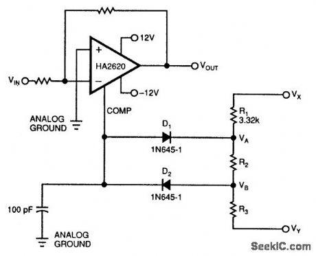
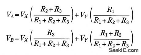
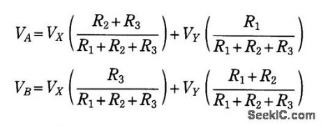
Adding a simple clamping circuit to a Harris 2620 high-speed op amp produces a glitch-free amplifier/ clipper. The op amp pin that controls the device's bandwidth is a high-impedance, isolated input. This pin also tracks the device's output voltage.Therefore, D1, D2, R1, R2, and R3 will clamp the amplifier's output voltage only when the amplifier's input voltage exceeds your clamping-voltage limits. VD is the diode drop of D1 or D2. The two clamp voltages, VA+VD and VB-VD, are:where VX and VY are the clamping circuit's bias voltages. Choosing R1 lets you determine the values of R2 and R3. Try a value for R1 around 3 kΩ.One example of this circuit had clamping voltages of ±3.7 V and exhibited THD below -75 dB for a sinusoidal, 30-kHz input signal. When the input signal increased beyond the ±3.7-V clamping voltage, the clipper symmetrically clamped the output voltage with no glitches in the waveform.
Reprinted Url Of This Article:
http://www.seekic.com/circuit_diagram/Basic_Circuit/GLITCH_FREE_CLIPPER.html
Print this Page | Comments | Reading(3)

Article Categories
power supply circuit
Amplifier Circuit
Basic Circuit
LED and Light Circuit
Sensor Circuit
Signal Processing
Electrical Equipment Circuit
Control Circuit
Remote Control Circuit
A/D-D/A Converter Circuit
Audio Circuit
Measuring and Test Circuit
Communication Circuit
Computer-Related Circuit
555 Circuit
Automotive Circuit
Repairing Circuit
Code: