Basic Circuit
GFI Ground Fault Interrupter Wall Wart
Published:2013/10/23 20:28:00 Author:lynne | Keyword: GFI Ground Fault Interrupter Wall Wart | From:SeekIC

I always wondered what was inside one of these clever devices, so I found one in my junk box and popped the lid—it was from a defunct blow hair dryer—never throw one of these away because the GFI unit long outlives the hair dryer and has many experimental uses. To get it apart, I had to make a special screw driver bit to remove the tamper resistant screws.
Inside was something that resembles a relay, a circuit board and a tiny current transformer. This did not happen by itself—that is why I cannot accept the theory of evolution—there was a designer!
The contacts resemble those of a relay, but are actuated manually via a button that protrudes through the cover, and released via a small solenoid operated plunger. There is a test pushbutton that operates a crude leaf contact on the small circuit board.
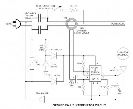
I traced out the circuit carefully and drew up the schematic. The IC is probably a variant of the Fairchild RV4141A or RV4145A because the pin out does not exactly agree with either device. Regardless, there are numerous ways of applying IC’s and the schematic in the application note is merely a guide. The current transformer is very likely a 1:1000 turns ratio device.
Ground Fault Interrupter Schematic
How it works
You will notice that the parallel power leads make a single turn through the primary of the current transformer (CT). The flux field of the source lead is cancelled by the flux field in the return lead so the net result is zero and the CT sees no primary current. Should these currents ever become unequal (as in a ground fault condition), the CT senses this difference and induces current into the 1000 turn secondary. The secondary current is low, but the load resistance is 1M, so it develops significant voltage. This voltage is sufficient to exceed the comparator threshold voltage of the IC and fire the SCR. When the SCR fires, it energizes the solenoid coil and jerks an iron slug toward the center of the coil. Attached to this iron slug is a stainless steel pin that actuates the mechanical release for the electrical contacts. When the contacts are open, the ground fault current is interrupted and the appliance is off-line. It remains off until the mechanical reset button is pressed.
Note that this is for an unbalanced fault condition in which the current flows to ground. It cannot provide protection for a balanced fault such as holding both ends of a suicide cord in either hand.
C1 prevents any DC bias current from flowing through the CT secondary. It does not take much primary current to saturate the core and degrade its performance. RV1 is a MOV transient suppressor—this is required to pass the 5000V UL/CSA/VDE transient voltage test.
There is also a small red wire that also goes through the CT opening—this is the test turn and it connects to a 15K resistor. When the test pushbutton is pressed, it connects the 15K resistor across the line and forces a low unbalanced current (7mA) through the primary. This low current simulates a limited ground fault condition that is similar to a mild electrical shock. Actual sensitivity is 4.8mA—I measured it by substituting various resistors. UL/CSA/VDE standards assume that anything below 5mA is non-life threatening.
Preventing nuisance trips is a requirement. This is what the 6.8uf gate to cathode capacitor is all about—it swamps out noise pulses, but charges up to the SCR gate voltage threshold when there is a real ground fault signal present.
Components to save for future experimentation
Current Transformer
Solenoid
SCR
Reprinted Url Of This Article:
http://www.seekic.com/circuit_diagram/Basic_Circuit/GFI_Ground_Fault_Interrupter_Wall_Wart.html
Print this Page | Comments | Reading(3)

Article Categories
power supply circuit
Amplifier Circuit
Basic Circuit
LED and Light Circuit
Sensor Circuit
Signal Processing
Electrical Equipment Circuit
Control Circuit
Remote Control Circuit
A/D-D/A Converter Circuit
Audio Circuit
Measuring and Test Circuit
Communication Circuit
Computer-Related Circuit
555 Circuit
Automotive Circuit
Repairing Circuit
Code: