Basic Circuit
GATED_PULSE_TRAIN
Published:2009/7/15 21:00:00 Author:Jessie | From:SeekIC

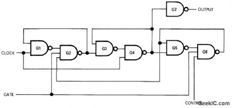
When control is logic 0, circuit transmits train of complete clock pulses to output, beginning with first clock pulse that starts to rise after application of gate signal and ending with last clock pulse that starts before gate signal falls. When control is logic 1, circuit transmits one complete clock pulse after logic 1 gate signal rises. To send another single pulse, gate signal must be removed and reapplied. Gates are Fairchild LPDT μL9047 triple three-input NAND and 9046 quad two-input NAND; other compatible DTL or TTL NAND gates can also be used.-J. V. Sastry, Gated Clock Generates Pulse Train or Single Pulse, EDN|EEE Magazine, July 1, 1971, p 50.
Reprinted Url Of This Article:
http://www.seekic.com/circuit_diagram/Basic_Circuit/GATED_PULSE_TRAIN.html
Print this Page | Comments | Reading(3)

Article Categories
power supply circuit
Amplifier Circuit
Basic Circuit
LED and Light Circuit
Sensor Circuit
Signal Processing
Electrical Equipment Circuit
Control Circuit
Remote Control Circuit
A/D-D/A Converter Circuit
Audio Circuit
Measuring and Test Circuit
Communication Circuit
Computer-Related Circuit
555 Circuit
Automotive Circuit
Repairing Circuit
Code: