Basic Circuit
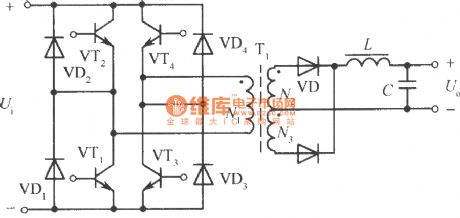
Full bridge power inversion circuit
Published:2011/11/14 2:35:00 Author:May | Keyword: Full bridge, power inversion | From:SeekIC

Full bridge inversion circuit is shown in the diagram and consists of suitable driver circuit and half bridge converter which hastwo electrolytic capacitors. Four bridge arms consist of VT1, VT2, VT3 and VT4. High frequency transformer T is connected in the middle of them. VT1, VT4 and VT2, VT3 on opposite arms is breaking over in turns by excitation of drive circuit. They can change DC input voltage to high frequency square wave AC voltage. Its working process is the same as push pull power converting circuit. So when high frequency transformer is working, the voltage gotten by its primary coil is power supply voltage. It is one time of half bridge circuit's output voltage, but each transistor's withstand voltage is still power supply voltage, so the output voltage is enlarging one time. If you want to let the current reach the level of half bridge circuit, the current shoule be enlarged one time, the output power can beenlarged four times.
The main shortcoming of full bridge circuit is that it needs four groups transistors base drive circuit which are isolatingfrom each other, so the control drive circuit is complex and expensive.
Reprinted Url Of This Article:
http://www.seekic.com/circuit_diagram/Basic_Circuit/Full_bridge_power_inversion_circuit.html
Print this Page | Comments | Reading(3)

Article Categories
power supply circuit
Amplifier Circuit
Basic Circuit
LED and Light Circuit
Sensor Circuit
Signal Processing
Electrical Equipment Circuit
Control Circuit
Remote Control Circuit
A/D-D/A Converter Circuit
Audio Circuit
Measuring and Test Circuit
Communication Circuit
Computer-Related Circuit
555 Circuit
Automotive Circuit
Repairing Circuit
Code: