Basic Circuit
Frequency adjustable bandpass filter circuit
Published:2011/6/23 22:05:00 Author:TaoXi | Keyword: Frequency adjustable, bandpass, filter | From:SeekIC
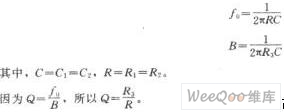

The frequency adjustable bandpass filter circuit is as shown in the figure. This filter's resonance frequency can be adjusted through the coaxial potentiometer, and the Q value will not change when you are adjusting the frequency. The Q value of the active band-pass filter of the figure is about 30, the resonant frequency can be changed from 150Hz to 1.5kHz, in this range the changing range of Q is less than 5%. For ease of the calculation, you need to set the potentiometer to the top, the resonant frequency f0 and the bandwidth B are:
Changing the position of the potentiometer is equivalent to add a voltage divider, so the current of R1, R2 and R3 reduce.
Reprinted Url Of This Article:
http://www.seekic.com/circuit_diagram/Basic_Circuit/Frequency_adjustable_bandpass_filter_circuit.html
Print this Page | Comments | Reading(3)

Article Categories
power supply circuit
Amplifier Circuit
Basic Circuit
LED and Light Circuit
Sensor Circuit
Signal Processing
Electrical Equipment Circuit
Control Circuit
Remote Control Circuit
A/D-D/A Converter Circuit
Audio Circuit
Measuring and Test Circuit
Communication Circuit
Computer-Related Circuit
555 Circuit
Automotive Circuit
Repairing Circuit
Code: