Basic Circuit
Frequency / voltage conversion circuit composed of TA7506
Published:2011/7/6 20:00:00 Author:Lucas | Keyword: Frequency conversion, voltage conversion | From:SeekIC
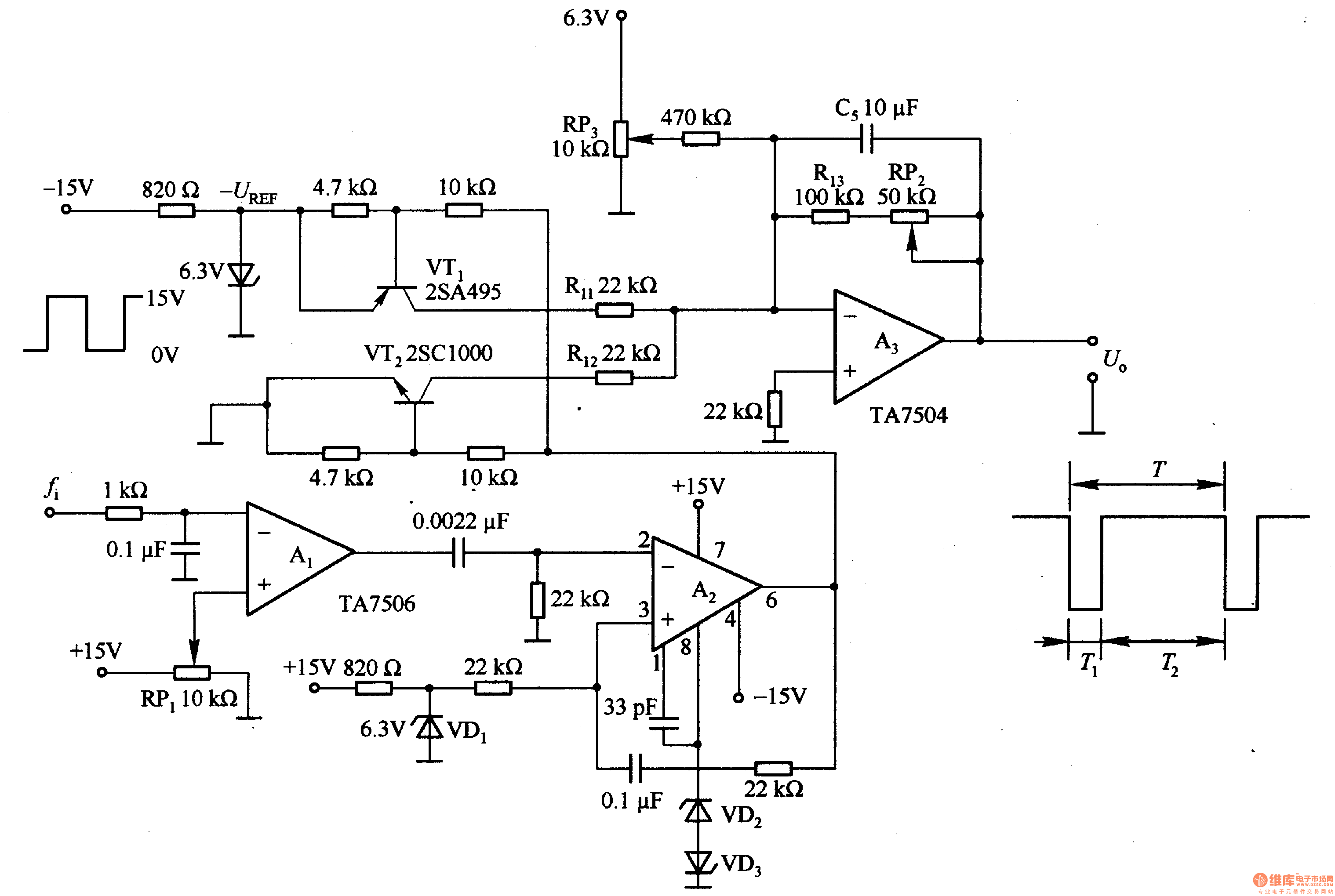
Al is the waveform shaping circuit, and A2 is the monostable multivibrator,then it gets a constant pulse width T2. VT1, VT2 and A3 constitute a frequency / voltage conversion circuit. In the T2 period, VTl turns on and integrates -U (REF) voltage; in the T1 period, VTl ends and VT2 conduction, the integrator A3 input voltage is OV. The C5, R3 and RP2 form low-pass filter, so A3 output is DC voltage. Adjusting the value of RP3 make fi = 12Hz, U. = OV; adjusting RP2 value make fi = 24Hz, U. = LV.
Reprinted Url Of This Article:
http://www.seekic.com/circuit_diagram/Basic_Circuit/Frequency___voltage_conversion_circuit_composed_of_TA7506.html
Print this Page | Comments | Reading(3)

Article Categories
power supply circuit
Amplifier Circuit
Basic Circuit
LED and Light Circuit
Sensor Circuit
Signal Processing
Electrical Equipment Circuit
Control Circuit
Remote Control Circuit
A/D-D/A Converter Circuit
Audio Circuit
Measuring and Test Circuit
Communication Circuit
Computer-Related Circuit
555 Circuit
Automotive Circuit
Repairing Circuit
Code: