Filter Circuit
the sawtooth-wave circuit of complementary tube
Published:2011/6/30 6:11:00 Author:Fiona | Keyword: sawtooth-wave, complementary tube | From:SeekIC
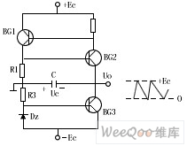
The picture shows the sawtooth-wave circuit of complementary tube.This is self-oscillating complementary sawtooth-wave circuit which the switching device is composed of BG1,BG2 and controls the timing capacitor C to charge and discharge,BG3 is constant flow pipe.When BG1, BG2 are closed, the constant current Ic3 charges to C(polarity is shown as the picture) the output voltage uo decreases with linear time, this is a scanning voltage positive process, when the capacitor voltage Uc drops to the BG2 conduction valve voltage, BG2 starts to conduct,BG1,BG2 arrive at the saturated state after a positive feedback chain reaction,at this time, when you reach a saturation point C remains at saturation without returning to the OFF state through BG1, BG2.
Reprinted Url Of This Article:
http://www.seekic.com/circuit_diagram/Basic_Circuit/Filter_Circuit/the_sawtooth_wave_circuit_of_complementary_tube.html
Print this Page | Comments | Reading(3)

Article Categories
power supply circuit
Amplifier Circuit
Basic Circuit
LED and Light Circuit
Sensor Circuit
Signal Processing
Electrical Equipment Circuit
Control Circuit
Remote Control Circuit
A/D-D/A Converter Circuit
Audio Circuit
Measuring and Test Circuit
Communication Circuit
Computer-Related Circuit
555 Circuit
Automotive Circuit
Repairing Circuit
Code: