Filter Circuit
complementary tube monostable circuit
Published:2011/6/30 6:35:00 Author:Fiona | Keyword: complementary tube, monostable | From:SeekIC
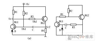
Picture shows the two forms of complementary tube monostable circuit, Figure (b) is complementary tube monostable circuit which the two tubes keep saturation in ordinary state. When it meets conditions,R2 <β1,R1 and R3 <β2, R4,the circuit is in two tubes steady states,when the negative pulse is used at the base BG1, BG1 is out of saturation, and causes a reaction Uc1 ↑ → Ub2 ↑ → Uc2 ↓ → Ub1 ↓.The result of a positive feedback chain reaction is that BG1, BG2 are closed, this is the temporary steady state.At this point C discharges to power supply through R2, R4,it enters two tube saturated stable state after discharging.Diode D is to prevent voltage of C puncturing BG1's base - emitter junction, the pulse width is:
tr=0.7(R2+R4)C
Reprinted Url Of This Article:
http://www.seekic.com/circuit_diagram/Basic_Circuit/Filter_Circuit/complementary_tube_monostable_circuit.html
Print this Page | Comments | Reading(3)

Article Categories
power supply circuit
Amplifier Circuit
Basic Circuit
LED and Light Circuit
Sensor Circuit
Signal Processing
Electrical Equipment Circuit
Control Circuit
Remote Control Circuit
A/D-D/A Converter Circuit
Audio Circuit
Measuring and Test Circuit
Communication Circuit
Computer-Related Circuit
555 Circuit
Automotive Circuit
Repairing Circuit
Code: