Basic Circuit
Electronic transformer with overcurrent protection circuit
Published:2014/2/6 21:44:00 Author:lynne | Keyword: Electronic transformer with overcurrent protection circuit, | From:SeekIC

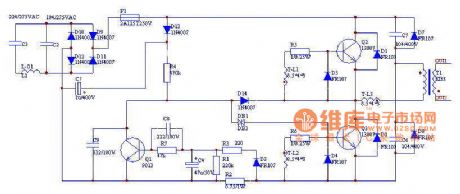
Electronic transformer with overcurrent protection circuit shown in Figure:
( 1 ) The core of the circuit is determined by C2, C3, T3, L3 trigger circuit with R2, double-ended C4, D7, L2 consists of two half-bridge circuit of the self-excited switching converter , which is a two-way trigger diode DB1 , the trigger voltage of 30V; T-L1-3 in the small high frequency magnetic ring ( diameter 7mm × 29mm × 12mm), the primary wire with a diameter of 0.50mm wound specifications lap 48 , the inductance of 9.5mH, with the secondary 30 diameter of 0.23mm enameled wire sizes from 5 laps , insulation between primary and secondary sets with suitable nylon , can be achieved CE safety standards.(2) Q1, C4, C5, R3, R4, D8, R8 composition overcurrent protection circuit , when the output level short circuit or overload , the voltage on resistor R2 will surge through D3, R3, R7, C8 divider Credit after triggering the transistor Q1 is turned on , so that the trigger switch can not be turned on and play a protective role , C4 role in protection from the state holding circuit.(3) C1, L1 arm consisting of LC type filter , fat filter spike pulse switch circuit. L1 wire with a diameter of 0.37mm specifications on the EE-20 types of high-frequency magnetic core made of 200 laps around the system . High-frequency magnetic core to be reserved between a gap to prevent core saturation , L1 inductance should be around well after about 6.9mH.(4) F1 is a fast-acting fuse to 800mA , R1 is varistors , F2 is the thermal insurance, should be installed and switch T2, T3 radiator connected together. The above elements can input circuit overcurrent , overvoltage protective effects and transistor overheating.(5) D5, D6, D8, D9, C6, C7 are output from the transformer L3 to the discharge peak inverse voltage applied .
Reprinted Url Of This Article:
http://www.seekic.com/circuit_diagram/Basic_Circuit/Electronic_transformer_with_overcurrent_protection_circuit.html
Print this Page | Comments | Reading(3)

Article Categories
power supply circuit
Amplifier Circuit
Basic Circuit
LED and Light Circuit
Sensor Circuit
Signal Processing
Electrical Equipment Circuit
Control Circuit
Remote Control Circuit
A/D-D/A Converter Circuit
Audio Circuit
Measuring and Test Circuit
Communication Circuit
Computer-Related Circuit
555 Circuit
Automotive Circuit
Repairing Circuit
Code: