Basic Circuit
ELEKTOR_ELECTRONICS
Published:2009/7/10 2:08:00 Author:May | From:SeekIC

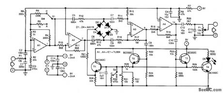
The control of this compressor is based on the dependence of the dynamic resistance of a diode on the current flowing through it. The heart of the present circuit is the diode bridge (D1 through D4), which behaves as a variable resistance controlled by the current flowing in T1.The input signal is applied to preamplifier state A1 via low-pass filter R1/C1 that removes any HF noise from the input.Switch S1 in the feedback loop of A1 sets the amplification to 1 (position A), 6 (C) or 11 (B). The amplified signal is applied directly to the diode bridge via R12 and C5, and inverted via inverter A2, capacitor C6 and resistor R13.The two signals are summed by the bridge, amplified (in A3), then split again into two, one of which is inverted by A4. The positive half cycles of the two signals are used to switch on T2 and T3, respectively. Capacitor C11 is then charged via R12. When the potential across this capacitor reaches a certain level, T1 is also switched on, after which a control current flows through the bridge via R21. This current lowers the resistance of the bridge so that the signal is attenuated (compressed). At the same time, the LED lights to indicate that the signal is being compressed. Capacitor C12 prevents any dc voltage from reaching the output.The output signal is taken from the wiper of P1. Low-pass section R20/C13 limits its bandwidth to 12 kHz. Switch S2 enables the selection of various decay times from C11. The values shown in the diagram are the most useful. Nevertheless, these values are subjective and can be altered to personal taste and requirements.
Reprinted Url Of This Article:
http://www.seekic.com/circuit_diagram/Basic_Circuit/ELEKTOR_ELECTRONICS.html
Print this Page | Comments | Reading(3)

Article Categories
power supply circuit
Amplifier Circuit
Basic Circuit
LED and Light Circuit
Sensor Circuit
Signal Processing
Electrical Equipment Circuit
Control Circuit
Remote Control Circuit
A/D-D/A Converter Circuit
Audio Circuit
Measuring and Test Circuit
Communication Circuit
Computer-Related Circuit
555 Circuit
Automotive Circuit
Repairing Circuit
Code: