Basic Circuit
Dual wave linear detector circuit
Published:2011/6/20 8:37:00 Author:Lucas | Keyword: Dual wave , linear, detector circuit | From:SeekIC

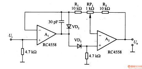
Dual wave linear detector circuit is shown as the chart. In the circuit, Ui is the AC input signal, and U is the rectifier output signal. In the positive half-cycle of AC input, A1's output is positive. As VD1 knife is positive bias, A2's input is positive, and its output is also positive, and it makes a feedback on A1 by R2, RPl and Rl, so A2 becomes a noninverting amplifier with the gain in 1; in the negative half-cycle of AC input, Al's output is also negative, and VD1 is anti-bias, then A2's inverting input is 0, that is, the working status of the inverting amplifier.
Reprinted Url Of This Article:
http://www.seekic.com/circuit_diagram/Basic_Circuit/Dual_wave_linear_detector_circuit.html
Print this Page | Comments | Reading(3)

Article Categories
power supply circuit
Amplifier Circuit
Basic Circuit
LED and Light Circuit
Sensor Circuit
Signal Processing
Electrical Equipment Circuit
Control Circuit
Remote Control Circuit
A/D-D/A Converter Circuit
Audio Circuit
Measuring and Test Circuit
Communication Circuit
Computer-Related Circuit
555 Circuit
Automotive Circuit
Repairing Circuit
Code: