Basic Circuit
Digital_auxiliary_boost_supply_kickstarter
Published:2009/7/24 11:56:00 Author:Jessie | From:SeekIC


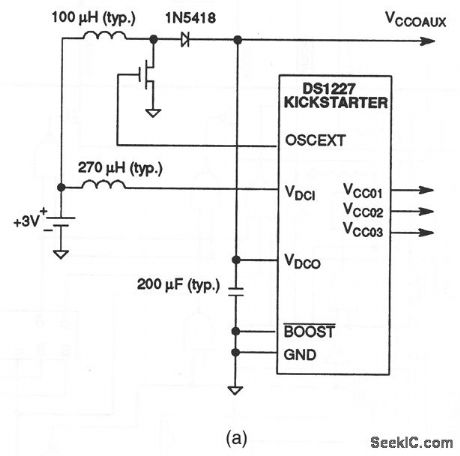
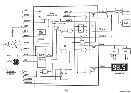
This circuit shows a DS1227 kickstarter chip connected to provide an auxiliary boost supply for digital systems. The DS1227 supplies 5 V on demand from either a 3- or 6-V battery input. The primary 5-V outputs, typically tied to a microcontroller VCC pin, is kickstarted on in response to any one of several possible momentary, external signal transitions. Examples of such signals include a clock/calendar alarm from a watchdog timer (Fig. 6-51), or an incoming asynchronous serial-data word from a host PC via a line-powered transceiver (Fig. 6-60), or a simple pushbutton switch. Figure 6-45B shows some typical kickstarter interconnections. Dallas Semiconductors, Product Data Book, 1992/1993, p. 10-17, 10-21.
Reprinted Url Of This Article:
http://www.seekic.com/circuit_diagram/Basic_Circuit/Digital_auxiliary_boost_supply_kickstarter.html
Print this Page | Comments | Reading(3)

Article Categories
power supply circuit
Amplifier Circuit
Basic Circuit
LED and Light Circuit
Sensor Circuit
Signal Processing
Electrical Equipment Circuit
Control Circuit
Remote Control Circuit
A/D-D/A Converter Circuit
Audio Circuit
Measuring and Test Circuit
Communication Circuit
Computer-Related Circuit
555 Circuit
Automotive Circuit
Repairing Circuit
Code: