Basic Circuit
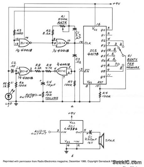
DOWNBEAT_EMPHASIZED_ELECTRONIC_METRONOME
Published:2009/7/8 2:12:00 Author:May | From:SeekIC

IC1a and IC1b form an astable multivibrator. The astable's signal is fed to IC1c, also to the clock input of IC2, a 4017B decade counter. That IC's Q0 through Q9 outputs become high one at a time for each successive clock pulse received at pin 14. Switch S1 feeds one of those outputs to the 4017B's reset input. Whenever the selected output becomes high, the 4017B restarts its counting cycle; that determines the number of beats per measure. The network composed of C2 and R6 sharpens the downbeat pulse, and the network composed of C3 and R7 sharpens the free-running pulses. By making C2 larger than C3, the downbeat receives greater emphasis.
Reprinted Url Of This Article:
http://www.seekic.com/circuit_diagram/Basic_Circuit/DOWNBEAT_EMPHASIZED_ELECTRONIC_METRONOME.html
Print this Page | Comments | Reading(3)

Article Categories
power supply circuit
Amplifier Circuit
Basic Circuit
LED and Light Circuit
Sensor Circuit
Signal Processing
Electrical Equipment Circuit
Control Circuit
Remote Control Circuit
A/D-D/A Converter Circuit
Audio Circuit
Measuring and Test Circuit
Communication Circuit
Computer-Related Circuit
555 Circuit
Automotive Circuit
Repairing Circuit
Code: