Basic Circuit
DIVIDER_FOR_7_MHz
Published:2009/7/6 3:05:00 Author:May | From:SeekIC

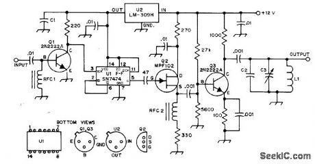
Used after 7-MHz VFO of 40-meter transmitter, to provide 3.5 MHz as required for operation in 80-meter band. Half of 7474 TTL D flip-flop Un is connected in divide-by-2 configuration. U2 provides required well-regulated 5-V source. Q1 clips negative-going portion of 7-MHz sine wave to prevent damage to 7474. Square-wave 3.5-MHz output from U1 is applied to source-follower Q2 which drives class A amplifier output stage Q3. RFC1 and RFC2 are 10 μH. C1 is 6.8-μF 10-V tantalum. Q2 is 100-pF mica. L1 is 41 turns No. 26 enamel spaced to fill entire 7-80-2 core,to give 10 ptH.-S. Creason, A VFO Frequency Divider, QST, Nov. 1976, p 23-24.
Reprinted Url Of This Article:
http://www.seekic.com/circuit_diagram/Basic_Circuit/DIVIDER_FOR_7_MHz.html
Print this Page | Comments | Reading(3)

Article Categories
power supply circuit
Amplifier Circuit
Basic Circuit
LED and Light Circuit
Sensor Circuit
Signal Processing
Electrical Equipment Circuit
Control Circuit
Remote Control Circuit
A/D-D/A Converter Circuit
Audio Circuit
Measuring and Test Circuit
Communication Circuit
Computer-Related Circuit
555 Circuit
Automotive Circuit
Repairing Circuit
Code: