Basic Circuit
DIGITAL_TACHOMETER_CIRCUITRY
Published:2009/7/10 2:06:00 Author:May | From:SeekIC


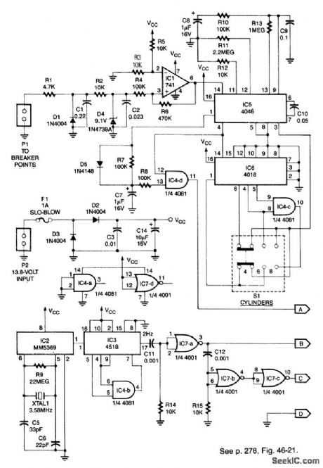
This system can be used with 4-, 6-, or 8-cylinder automobiles. The timebase formed by IC5 is an oscillator that drives counter IC6, which divides by 6, 4, or 3 for 4-, 6-, or 8-cylinder engines, respectively.S1 selects this number IC5 produces a signal that is phaselocked to this multiple of the ignition system frequency, which in turn depends on engine speed.
ICl conditions the ianition input at PI to feed IC5. The output of IC4D, which is the same frequency as the VC0 in IC5, is fed to the frequency display.
IC2 generates a 60-Hz sianal using a 3.58-MHz reference. IC3 and IC4B divide this by 30 to produce 2Hz. IC7B/IC7C and C12/R15 produce a delayed 2-Hz signal. These sianals are fed to the counter circuit.
Reprinted Url Of This Article:
http://www.seekic.com/circuit_diagram/Basic_Circuit/DIGITAL_TACHOMETER_CIRCUITRY.html
Print this Page | Comments | Reading(3)

Article Categories
power supply circuit
Amplifier Circuit
Basic Circuit
LED and Light Circuit
Sensor Circuit
Signal Processing
Electrical Equipment Circuit
Control Circuit
Remote Control Circuit
A/D-D/A Converter Circuit
Audio Circuit
Measuring and Test Circuit
Communication Circuit
Computer-Related Circuit
555 Circuit
Automotive Circuit
Repairing Circuit
Code: