Basic Circuit
DELAYED_VOX
Published:2009/7/20 3:06:00 Author:Jessie | From:SeekIC

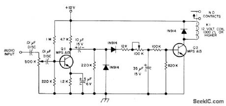
Minimizes unintentional triggering of repeater by using timer requiring 3 s of continuous carrier and audio on input receiver of repeater to turn on transmitter. Repeater is then controlled by its own carrier-operated relay until 20-s lapse in transmission occurs. System then requires another3-s carrier to restore normal operation, Q1 is common-emitter amplifier with gain adjusted by 500K pot. Audio peaks from al feed full-wave diode detector through 10-ptF electrolytic. Series resistance in path through 35-ptF electrolytic controls its charge-up time and thus controls delay of relay pickup. Adjust 100K pot to give desired turn-on delay in range from fraction of second to about 4 s. Resistance divider shown provides relay dropout delay of about 20 s, which pre-vents VOX circuit from dropping out repeater during lapses in speech.-J. Everhart, A Delayed VOX for Repeaters, 73 Magazine, April 1974, p 17 and 19-20.
Reprinted Url Of This Article:
http://www.seekic.com/circuit_diagram/Basic_Circuit/DELAYED_VOX.html
Print this Page | Comments | Reading(3)

Article Categories
power supply circuit
Amplifier Circuit
Basic Circuit
LED and Light Circuit
Sensor Circuit
Signal Processing
Electrical Equipment Circuit
Control Circuit
Remote Control Circuit
A/D-D/A Converter Circuit
Audio Circuit
Measuring and Test Circuit
Communication Circuit
Computer-Related Circuit
555 Circuit
Automotive Circuit
Repairing Circuit
Code: