Basic Circuit
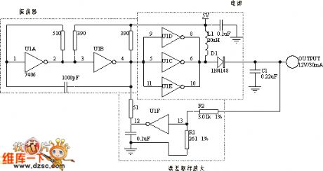
DC / DC converter circuit diagram using six inverter
Published:2012/9/18 2:28:00 Author:Ecco | Keyword: DC / DC converter , six inverter | From:SeekIC

The circuit can be used to adjust voltage by TTL switch threshold. U1A and U1B form the oscillator, and its switching frequencies < 1MHz. The output of the oscillator can drive the three parallel inverters U1C, U1D U1E to provide a higher output current and output power. Its internal output transistor, L1 and D1 form a standard boost converter, when its output is low, the current only flows through the inductor L1; when the output becomes high, the energy stored in the inductor makes anode of D1 become high, D1 conduction charges for C1. The circuit and load characteristics are better than 1%, and output voltage only changes 7% in range of 0 ℃ ~ 50 ℃.
Reprinted Url Of This Article:
http://www.seekic.com/circuit_diagram/Basic_Circuit/DC___DC_converter_circuit_diagram_using_six_inverter.html
Print this Page | Comments | Reading(3)

Article Categories
power supply circuit
Amplifier Circuit
Basic Circuit
LED and Light Circuit
Sensor Circuit
Signal Processing
Electrical Equipment Circuit
Control Circuit
Remote Control Circuit
A/D-D/A Converter Circuit
Audio Circuit
Measuring and Test Circuit
Communication Circuit
Computer-Related Circuit
555 Circuit
Automotive Circuit
Repairing Circuit
Code: