Basic Circuit
DC_SERVO_DRIVE_EMPLOYS_BIPOLAR_CONTROL_INPUT
Published:2009/7/5 21:41:00 Author:May | From:SeekIC

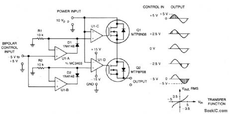
This circuit accepts bipolar control inputs of ±5 V and provides a phase-chopped output to a dc load (such as a servo motor) of the same polarity as the input. The rms voltage of the output is closely proportional to the control input voltage.
N-channel and p-channel TMOS devices, Q1 and Q2, are connected in anti-series to form a bidirectional switch through which current can flow in either the forward or reverse direction. Control circuits turn Q1 and Q2 on when they are reverse biased, bypassing their reverse rectif er and increasing circuit efflciency. Each device is allowed to turn off only when forward biased.
The Q1-Q2 switch connects the ac power source to the load when its instantaneous voltage is the same polarity and less than the control voltage. U1a is conftgured as an ideal positive rectifter whose output follows the control voltage when it is positive, and is zero otherwise. Similarly, U1b is a negative rectifier. U1c tums Q1 on whenever the ac input voltage is lower than the positive rectifier output. For negative control voltages, Q1 is turned on only during the negative half-cycle. For positive control voltages, Q1 is tumed on during the end portions of the positive half-cycle. Similarly, U1d turns Q2 on whenever the ac input voltage is higher than the output of the negative rectifier.
Reprinted Url Of This Article:
http://www.seekic.com/circuit_diagram/Basic_Circuit/DC_SERVO_DRIVE_EMPLOYS_BIPOLAR_CONTROL_INPUT.html
Print this Page | Comments | Reading(3)

Article Categories
power supply circuit
Amplifier Circuit
Basic Circuit
LED and Light Circuit
Sensor Circuit
Signal Processing
Electrical Equipment Circuit
Control Circuit
Remote Control Circuit
A/D-D/A Converter Circuit
Audio Circuit
Measuring and Test Circuit
Communication Circuit
Computer-Related Circuit
555 Circuit
Automotive Circuit
Repairing Circuit
Code: