Basic Circuit
Current negative feedback bias circuit
Published:2011/6/28 1:29:00 Author:Christina | Keyword: Current, negative feedback, bias circuit | From:SeekIC

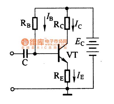
The current negative feedback bias circuit is as shown in the figure. The difference between this circuit and the fixed bias circuit is the semiconductor transistor emitter is connected with a resistance RE. The parameters of this circuit are: Ec=IERE+UBE+IBRB.
As the EC power is constant, if the IERE increases, the UBE will decreases, so the IB decreases too. The process of the circuit stable quiescent operating point is:
↑-->Ic↑-->IE↑-->IERE↑-->UBE↓-->IB↓-->IC↓
Figure: Current negative feedback bias circuit
Reprinted Url Of This Article:
http://www.seekic.com/circuit_diagram/Basic_Circuit/Current_negative_feedback_bias_circuit.html
Print this Page | Comments | Reading(3)

Article Categories
power supply circuit
Amplifier Circuit
Basic Circuit
LED and Light Circuit
Sensor Circuit
Signal Processing
Electrical Equipment Circuit
Control Circuit
Remote Control Circuit
A/D-D/A Converter Circuit
Audio Circuit
Measuring and Test Circuit
Communication Circuit
Computer-Related Circuit
555 Circuit
Automotive Circuit
Repairing Circuit
Code: