Basic Circuit
Color TV pincushion correction circuit diagram 5
Published:2011/6/23 22:26:00 Author:Ecco | Keyword: Color TV , pincushion correction | From:SeekIC
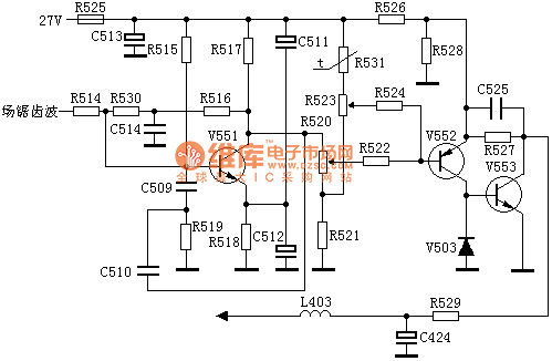
Field sawtooth wave signal is sent to the the V551's base of R514, integrated by the R516, C514, differentiated by E-B pole of C510, R519, C509, V551 to generate parabolic wave signal, and then amplified signal by V552 will be output from the collector, and directly sent to the base of V553. The parabolic wave signal output by from V553 collector is added to the negative side of V402 by R529, L403, then the V401 modulates the line deflection coil current, then the East / West pincushion distortion is corrected. The signal added on the R520 is the parabolic wave signal, and adjusting R520 can change parabolic wave signal amplitude, thus regulate the amount of the pincushion correction.
Reprinted Url Of This Article:
http://www.seekic.com/circuit_diagram/Basic_Circuit/Color_TV_pincushion_correction_circuit_diagram_5.html
Print this Page | Comments | Reading(3)

Article Categories
power supply circuit
Amplifier Circuit
Basic Circuit
LED and Light Circuit
Sensor Circuit
Signal Processing
Electrical Equipment Circuit
Control Circuit
Remote Control Circuit
A/D-D/A Converter Circuit
Audio Circuit
Measuring and Test Circuit
Communication Circuit
Computer-Related Circuit
555 Circuit
Automotive Circuit
Repairing Circuit
Code: