Basic Circuit
CURVE_TRACER
Published:2009/7/11 4:02:00 Author:May | From:SeekIC


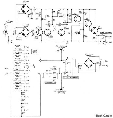
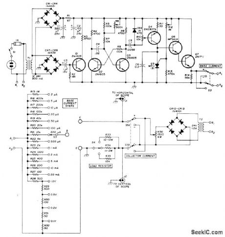
Displays on CRO a family of six collector characteristics for transistors and voltage/current characteristics of diodes, Circuit varies base voltage in discrete steps while sweeping collector voltage from zero to maximum at each step. Collector voltage is 120-Hz rectified sine wave from bridge rectifier CR10 CR13, varied by R36. S5 selects proper polarity. Base voltage steps are synchronized to 120-Hz colleetor voltage by adjusting R6 in mono MVBR Q2-Q3 driven by Q1. R10 adjusts voltage between steps. Programmable UJT Q5 resets staircase generator to zero. R12 adjusts gate voltage. Staircase voltage is coupled to bias resistors R15-R32 fortest transistor by Q6 and Q7, with bias polarity and value selected by S2 and S3. Connect device undertest to points B, C, and E. Connect points A1 and A2 together. R15-R35 should have 5% accuracy.-D. Wright, Transistor Curve Tracer, Ham Radio, July 1973, p 52-55.
Reprinted Url Of This Article:
http://www.seekic.com/circuit_diagram/Basic_Circuit/CURVE_TRACER.html
Print this Page | Comments | Reading(3)

Article Categories
power supply circuit
Amplifier Circuit
Basic Circuit
LED and Light Circuit
Sensor Circuit
Signal Processing
Electrical Equipment Circuit
Control Circuit
Remote Control Circuit
A/D-D/A Converter Circuit
Audio Circuit
Measuring and Test Circuit
Communication Circuit
Computer-Related Circuit
555 Circuit
Automotive Circuit
Repairing Circuit
Code: