Basic Circuit
CONTROL_FUNCTION_DECODER
Published:2009/7/20 3:07:00 Author:Jessie | From:SeekIC

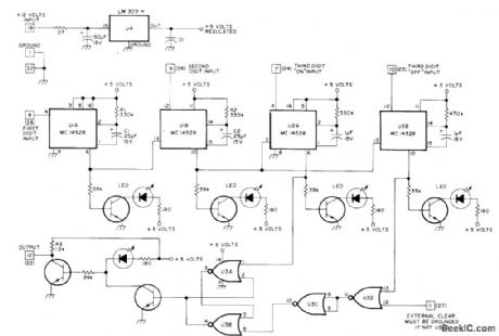
Circuit detects predetermined 3-digit sequence of Touch-Tone signals and sets flip-flop to provide required output for activating desired function.Another 3-digit sequence, differing in only third digit, resets flip-flop for turning off controlled device. Circuit uses two dual mono MVBRs. Output of U1A goes to reset terminal of U1B.Output of U1B goes to reset terminals of monos U2A and U2B. Mono outputs drive RS flip-flop to provide output required for desired control fu notion, such as control of autopath, switching repeater mode from carrier to tone-access, and switching to remote receiver. Q1-Q6 can be almost any NPN silicon transistors, such as 2N3904. U3 can be MC14001 or CD4001. Numbers in boxes and parentheses refer to edge connector pins.-T. E. Doyle, Control Function Decoder, Ham Radio, March 1977, p 66-67.
Reprinted Url Of This Article:
http://www.seekic.com/circuit_diagram/Basic_Circuit/CONTROL_FUNCTION_DECODER.html
Print this Page | Comments | Reading(3)

Article Categories
power supply circuit
Amplifier Circuit
Basic Circuit
LED and Light Circuit
Sensor Circuit
Signal Processing
Electrical Equipment Circuit
Control Circuit
Remote Control Circuit
A/D-D/A Converter Circuit
Audio Circuit
Measuring and Test Circuit
Communication Circuit
Computer-Related Circuit
555 Circuit
Automotive Circuit
Repairing Circuit
Code: