Basic Circuit
CONSTANT_CURRENT_STIMULATOR
Published:2009/7/8 2:10:00 Author:May | From:SeekIC


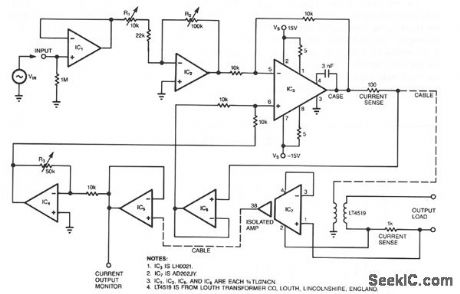
Most circuits that provide an electrical stimulus for research subjects are constant-voltage designs; this circuit is a constant-current design. Stimulator circuits must be isolated for two reasons: to ensure safety and to minimize interference. Isolated stimulators are essentially two-terminal devices; output currents can flow only between the two output terminals and can at no time flow through any other path, such as the power ground.
The circuit's bandwidth ranges from 50 Hz to 5 kHz when a ± 1 V sinusoidal input drives the circuit.Output loads can range from a short circuit to 100 KΩ and have as much as 0.033 μF of parallel capacitance. The transformer and associated circuitry conveniently connect to the main circuit via a cable. Note: This circuit is not approved for use on human beings.
Op amps, IC1 and IC2, buffer and set the gain of the circuit, respectively. You adjust trimmer R1 so that R2, a 10-turn pot, yields output currents ranging from 0 to 1 mA/VIN. IC3 is a power op amp. Its output drives the primary of a transformer that has a current gain of 0.1, or avoltage gain of10. Operating from a + 15 V supply, the transformer therefore has a voltage compliance of ±150 V.
The circuit senses not only the current supplied to the transformer but also the current in the transformer's secondary. IC7, a fully isolated, medical-grade amplifier, provides the isolated feedback signal because the op amp has its own built-in isolation transformer. Trimmer R3 sets the feedback gain precisely at 27 KΩ nominal.
Reprinted Url Of This Article:
http://www.seekic.com/circuit_diagram/Basic_Circuit/CONSTANT_CURRENT_STIMULATOR.html
Print this Page | Comments | Reading(3)

Article Categories
power supply circuit
Amplifier Circuit
Basic Circuit
LED and Light Circuit
Sensor Circuit
Signal Processing
Electrical Equipment Circuit
Control Circuit
Remote Control Circuit
A/D-D/A Converter Circuit
Audio Circuit
Measuring and Test Circuit
Communication Circuit
Computer-Related Circuit
555 Circuit
Automotive Circuit
Repairing Circuit
Code: