Basic Circuit
CAR_STEREO_SUBWOOFER_CROSSOVER
Published:2009/7/13 2:21:00 Author:May | From:SeekIC

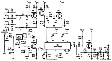
This figure is the schematic for the subwoofer crossover. The inputs through Q1 form a differential summing amplifier, with switch S1 functioning as a polarity inverter. A 24-dB-peroctave switched capacitor filter (IC1) is the heart of the continuously variable filter. Potentiometer R13 controls the cutoff frequency of IC1 by controlling its sampling frequency. Because of the in-herent sampling action of switched capacitor filters, an antialiasing filter is required at the input of IC1. Transistors Q2 and Q3, along with the surrounding components, form this second-order low-pass antialiasing filter. The subsonic filter with a boost stage follows the output of IC1 at 5. When switch S2 is closed, the boost is added. Additional subsonic filtering action is provided by C1 and C2 at the inputs of the crossover circuit. A reconstruction filter that eliminates sampling artifacts is formed by R18 and C10 at the output of IC1. The power-supply circuit, based on the 78L08 voltage regulator (IC2), provides both an 8.6-V main supply and a 4.8-V bias supply. Diode D1 protects against negative voltage spikes and incorrect hookup. Diode D2 biases the 78L08 regulator reference pin at 0.6 V to provide an output of 8.6 V, rather than 8 V.
Reprinted Url Of This Article:
http://www.seekic.com/circuit_diagram/Basic_Circuit/CAR_STEREO_SUBWOOFER_CROSSOVER.html
Print this Page | Comments | Reading(3)

Article Categories
power supply circuit
Amplifier Circuit
Basic Circuit
LED and Light Circuit
Sensor Circuit
Signal Processing
Electrical Equipment Circuit
Control Circuit
Remote Control Circuit
A/D-D/A Converter Circuit
Audio Circuit
Measuring and Test Circuit
Communication Circuit
Computer-Related Circuit
555 Circuit
Automotive Circuit
Repairing Circuit
Code: