Basic Circuit
Basic_piezo_ceramic_based_filter
Published:2009/7/24 12:55:00 Author:Jessie | From:SeekIC
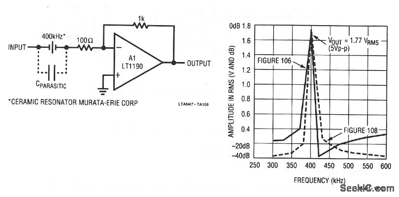
This circuit is a highly selective bandpass filter that uses a resonant ceramic element and a single amplifier. The ceramic element looks like a high impedance off the resonant frequency (400 kHz, in this case). At resonance, the ceramic element has a low impedance, and A1 responds as an inverter with gain. As shown, the ceramic element has stray or parasitic capacitance that causes a slight rise in output at frequencies above 425 kHz. Typically, the A1 output is down about 20 dB at 300 kHz and 40 dB at 425 kHz. The parasitic capacitance can be minimized with a differential network (Fig. 7-11). Linear Technology Corporation, 1991, AN47-48.
Reprinted Url Of This Article:
http://www.seekic.com/circuit_diagram/Basic_Circuit/Basic_piezo_ceramic_based_filter.html
Print this Page | Comments | Reading(3)

Article Categories
power supply circuit
Amplifier Circuit
Basic Circuit
LED and Light Circuit
Sensor Circuit
Signal Processing
Electrical Equipment Circuit
Control Circuit
Remote Control Circuit
A/D-D/A Converter Circuit
Audio Circuit
Measuring and Test Circuit
Communication Circuit
Computer-Related Circuit
555 Circuit
Automotive Circuit
Repairing Circuit
Code: