Analog Circuit
SCOPE_VOLTAGE_CURSOR_ADAPTER
Published:2009/6/23 2:39:00 Author:May | From:SeekIC
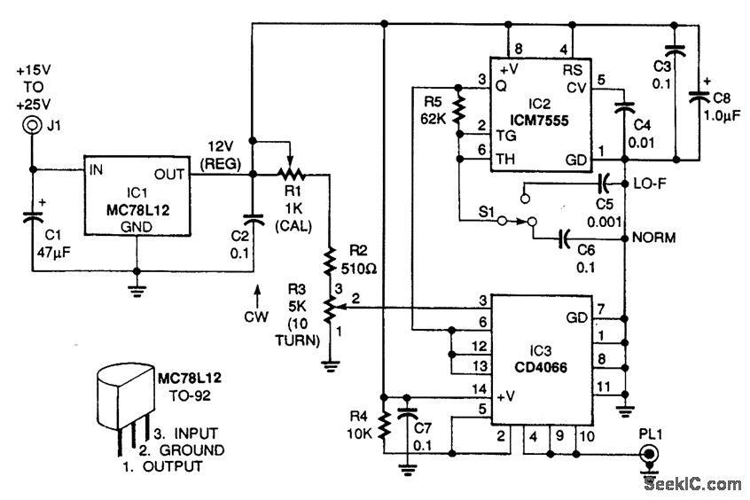
The voltage cursor adapter superimposes horizontal cursor lines on the top and bottom of the waveform-a kind of electronic calipers-to perrrtit direct readout of the voltage value. The cursor lines extend across the entire screen. The MC78L12 voltage regulator (IC1) supplies regulated 12 Vdc to the rest ofthe circuit. The ICM7555 timer (IC2) drives the CD4066B, a CMOS bilateral switch (IC3). This drive frequency can either be a normal frequency (NORM) of 100 Hz or a low-frequency (LO-F) of 10 kHz, depending on the setting of switch S1. Set S1 to LO-F for inputs below 500 Hz.The dc reference voltage supplied to pin 3 of IC3 is set by R3, a 10-turn, 5000-Ω precision potentiometen The voltage can be read directly from a turns counter dial coupled directly to the potentiometer's wiper. The accuracy of this reading can be 1% or better. Trimmer potentiometer R1 permits the voltage to R3 to be calibrated to precisely 10 V.The circuit is calibrated by setting the digital reading on the turns counter of R3 to the full clockwise position and adjusting R1 for a reading of 10 V at the wiper of R3 with a digital voltmeter.Bilateral switch IC3 converts the dc reference to a square wave with exactly the same wiper amplitude. The square-wave output appears on common pins 4, 9, and 10 of IC3 and coaxial plug PL1.
Reprinted Url Of This Article:
http://www.seekic.com/circuit_diagram/Basic_Circuit/Analog_Circuit/SCOPE_VOLTAGE_CURSOR_ADAPTER.html
Print this Page | Comments | Reading(3)

Article Categories
power supply circuit
Amplifier Circuit
Basic Circuit
LED and Light Circuit
Sensor Circuit
Signal Processing
Electrical Equipment Circuit
Control Circuit
Remote Control Circuit
A/D-D/A Converter Circuit
Audio Circuit
Measuring and Test Circuit
Communication Circuit
Computer-Related Circuit
555 Circuit
Automotive Circuit
Repairing Circuit
Code: