Basic Circuit
A Full and Half-Wave DC Test Throttle
Published:2013/6/25 21:59:00 Author:muriel | Keyword: Full, Half-Wave, DC Test Throttle | From:SeekIC

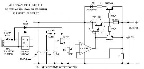
The next throttle is one that was put together for testing purposes only. As can be seen it is a modification of the basic transistor throttle shown above. The SPDT switch allows the throttle to have a full or half wave DC output.
The value of the 8 uF capacitors is calculated to allow the voltage across the 1000 ohm potentiometer to decay to 1/3 of the supply voltage before the next cycle starts. At 120 Hz; 8 uF is needed and at 60 Hz; 16 uF is required to achieve this result.
This means that the peak output voltage of the throttle has value that is three times the lowest voltage of the output for a given throttle setting. Please refer to the wave forms diagram below the schematic for clarification.If the 8 uF capacitors are omitted, the circuit becomes an overly-complicated, fullwave DC throttle.
The throttle as shown has an automatic current limiting of about 2 amps and a quasi-regulated output voltage.
This throttle gave pretty good results with an Atlas locomotive and one from a starter set of the type that make their appearance at Christmas time.
Reprinted Url Of This Article:
http://www.seekic.com/circuit_diagram/Basic_Circuit/A_Full_and_Half_Wave_DC_Test_Throttle.html
Print this Page | Comments | Reading(3)

Article Categories
power supply circuit
Amplifier Circuit
Basic Circuit
LED and Light Circuit
Sensor Circuit
Signal Processing
Electrical Equipment Circuit
Control Circuit
Remote Control Circuit
A/D-D/A Converter Circuit
Audio Circuit
Measuring and Test Circuit
Communication Circuit
Computer-Related Circuit
555 Circuit
Automotive Circuit
Repairing Circuit
Code: