Basic Circuit
AUTOMOTIVE_EXHAUST_EMISSIONS_ANALYZER
Published:2009/7/2 4:49:00 Author:May | From:SeekIC

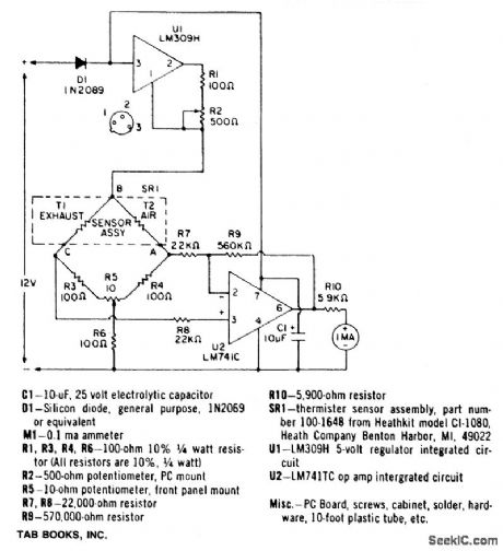
A bridge circuit contains two 100-ohm resistors (R3 and R4), and two thermistors (T1 and T2). At room temperature the resistance of T1 and T2 is about 2000 ohms. When they are each heated to 150℃ by a 10 mA current, the resistance value decreases to 100 ohms. Thus, the four elements comprise a bridge circuit. A characteristic of CO is that it conducts heat away from a thermistor at a different rate than air. One thermistor, T1, is exposed to the automobile exhaust while the other, T2, is isolated in a pure air environment. The difference in thermal conduction unbalances the bridge. A voltage difference is caused between points A and C. A differential amplifier, U1, amplifies this difference and drives the meter with sufficient current to read out the percentage of CO and the air-fuel ratio. A front panel balance control, R5, balances the bridge and calibrates the instrument. Calibration is performed when both thermistors are exposed to the outside air.
Reprinted Url Of This Article:
http://www.seekic.com/circuit_diagram/Basic_Circuit/AUTOMOTIVE_EXHAUST_EMISSIONS_ANALYZER.html
Print this Page | Comments | Reading(3)

Article Categories
power supply circuit
Amplifier Circuit
Basic Circuit
LED and Light Circuit
Sensor Circuit
Signal Processing
Electrical Equipment Circuit
Control Circuit
Remote Control Circuit
A/D-D/A Converter Circuit
Audio Circuit
Measuring and Test Circuit
Communication Circuit
Computer-Related Circuit
555 Circuit
Automotive Circuit
Repairing Circuit
Code: