Basic Circuit
AUTOMOBILE_IGNITION_SUBSTITUTE
Published:2009/7/6 2:14:00 Author:May | From:SeekIC

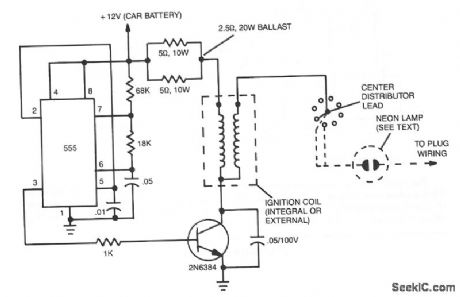
The ignition substitute provides a constant power source for the ignition coil. Its frequency, 0.5- 1.0 kHz, is that used by an 8-cylinder engine with an idling speed of 650 RPM, and the unit provides a rapid spark at a 17% duty cycle, while staying within the power dissipation limits of the components.
The circuit consists of a 555 timer IC configured as an astable free-running multivibrator that is used to drive a high-current npn transistor, such as a 2N6384. The transistor should be heavily heatsinked because it might be drawing several amps over quite a long period of time.
The coil ballast can be from 0.68 to 6.5Ω, depending on what's available. The 2.5-Ω, 20-W ballast shown works well. All the other resistors can be either 1/4- or 1/2-W devices, and the capacitor, between pins 1 and 5 of the 555, can range from 0.01 to 0.05 μF. Do not omit the 100-V, 0.05-μF capacitor across the transistor; it prevents voltage spikes from damaging the device.
Although designed for an 8-cylinder engine, this device can be used with other types. In addition,a neon bulb can be added to the circuit to verify the presence of a spark.
Reprinted Url Of This Article:
http://www.seekic.com/circuit_diagram/Basic_Circuit/AUTOMOBILE_IGNITION_SUBSTITUTE.html
Print this Page | Comments | Reading(3)

Article Categories
power supply circuit
Amplifier Circuit
Basic Circuit
LED and Light Circuit
Sensor Circuit
Signal Processing
Electrical Equipment Circuit
Control Circuit
Remote Control Circuit
A/D-D/A Converter Circuit
Audio Circuit
Measuring and Test Circuit
Communication Circuit
Computer-Related Circuit
555 Circuit
Automotive Circuit
Repairing Circuit
Code: