Basic Circuit
AUTOMATIC_LIGHT_BULB_CHANGER
Published:2009/7/9 23:15:00 Author:May | From:SeekIC

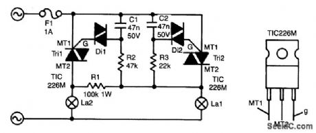
The circuit presented here guarantees that if bulb La1 gives up the ghost, bulb La2 will take over its task. In series with La1 is triac Tri2. Resistor R3 and C2 form a delay network. As soon as the voltage across C2 rises above about 30 V, diac (gateless triac) D2 is switched on, which causes Tri2 to conduct so that La1 lights.
The control circuit of La2 is parallel to that of La1, but because R2/C1 has twice the delay of R3/C2, Tri1 will not be triggered when Tri2 conducts; C1 discharges so that Tri1 cannot be triggered.
When, however, La1 is open-circuited, a voltage is across both RC networks via La2 and RI. Again, Tri2 will be triggered first, but because the current is smaller than its holding current, it will cease to conduct almost immediately. Capacitor C1 will then continue to charge and after a little while Tri1 is switched on.
Because the time constant for La2 is somewhat longer than that for La1, La2 will always be slightly less bright than La1. It is, of course, possible to give La2 a slightly higher wattage than La1 to ensure equal brightness.
Without heatsinks, the triacs can handle up to 100 W each; with heatsinks, powers of up to 1 000W can be accommodated. It is not recommended to use bulbs with a wattage below 25W, because these can flicker.
The triacs can be any type that can handle at least 400 V at no less than 5A. The M types used in the prototype can handle 600 V at 5A.
Reprinted Url Of This Article:
http://www.seekic.com/circuit_diagram/Basic_Circuit/AUTOMATIC_LIGHT_BULB_CHANGER.html
Print this Page | Comments | Reading(3)

Article Categories
power supply circuit
Amplifier Circuit
Basic Circuit
LED and Light Circuit
Sensor Circuit
Signal Processing
Electrical Equipment Circuit
Control Circuit
Remote Control Circuit
A/D-D/A Converter Circuit
Audio Circuit
Measuring and Test Circuit
Communication Circuit
Computer-Related Circuit
555 Circuit
Automotive Circuit
Repairing Circuit
Code: