Basic Circuit
AUDIBLE_METER_READER
Published:2009/7/3 2:56:00 Author:May | From:SeekIC

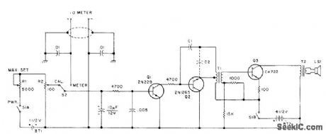
Analog meter terminals are connected to input of DC amplifier Q1 for feeding audio oscillator Q2 and output amplifier Q3. Frequency of oscillator is directly proportional to reading of meter. At calibrate position of S2, DC amplifier is fed by voltage divider R1-R2 and R2 is adjusted until tones heard are identical for both positions of S2. Developed for use by blind person. Knob of R2 sweeps over large scale having markings in Braille for reading of setting at which tones match. Alternatively, R2 can be preset to desired reading and equipment under test adjusted to give tone match. Article covers construction and calibration. C1 is chosen in range of 0.002 to 0.1 μF to give desired minimum fre quency. C2, if required, is in same range. T1 is transistor driver transformer (10,000 to 2000 ohms), and T2 is transistor output transformer (500 to 3.2 ohms).-N .Rosenberg, Tune-UpAids forthe Blind.73Magazine, Feb,1978,p64-67.
Reprinted Url Of This Article:
http://www.seekic.com/circuit_diagram/Basic_Circuit/AUDIBLE_METER_READER.html
Print this Page | Comments | Reading(3)

Article Categories
power supply circuit
Amplifier Circuit
Basic Circuit
LED and Light Circuit
Sensor Circuit
Signal Processing
Electrical Equipment Circuit
Control Circuit
Remote Control Circuit
A/D-D/A Converter Circuit
Audio Circuit
Measuring and Test Circuit
Communication Circuit
Computer-Related Circuit
555 Circuit
Automotive Circuit
Repairing Circuit
Code: