Basic Circuit
ADC_with_sample_rand_hold_S_H
Published:2009/7/25 5:00:00 Author:Jessie | From:SeekIC

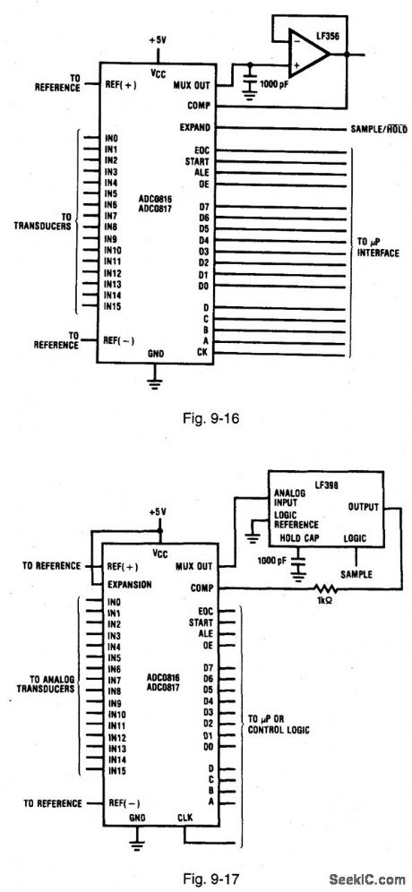
Figures 9116 and 9-17 show the ADC0816/17 connected for S/H operation. (The S/H function is the only major data-acquisition element not included in these ADCs.) If the input signals are fast moving, then an S/H should be used to quickly acquire the signal, then hold the signal while the ADCs convert it to a digital readout. This can be implemented by inserting an S/H function between the multiplexer output and the comparator input. In the simplest form, the multiplexer output is connected to the comparator input, with a capacitor connected to ground (similar to that shown in Fig. 9-16). The expansion-control pin is used as a sample-control input. When EXPAND is high, one switch is on and the capacitor voltage follows the input. When EXPAND is low, all switches are turned off and the capacitor holds the last value. However, this simple solution is not practical. The input bias to the comparator is about 2 μA (worst case, with a clock of 640 kHz). The droop (discharge rate) for a 1000-pF capacitor is about 2000 V/s (about 0.2-V per conversion). This is not practical. If a 0.01-μF capacitor is used instead, the rate is about 20 μV, which might work. However, the acquisition time would be about 100 μs, about the length of a conversion. The circuit of Fig. 9-16 eliminates the problem produced by the high comparator-input leakage. With the LF356 buffer connected between the multiplexer-output and comparator input pins, the leakage is reduced from 2 μA to about 100 nA. The droop-per-conversion is typically less than 1.0 μV per conversion (with the 1000-μF capacitor shown) and the acquisition time is about 20 ps (instead of the 100 ps). The circuit of Fig. 9-16 isolates the capacitor from both the multiplexer and comparator pins using an LF398 IC sample-and-hold. Acquisition time for the LF398 is a typical 4 μs to (0.1%), and droop rate is about 20 μV/conversion. Because the LF398 has its own S/H input, the expansion control of the ADC is free to be used in the normal manner. Use a hold capacitor with minimum dielectric absorption (polypropylene and polystyrene) for best results. NATIONAL SEMICONDUCTOR, APPLICATION NOTE 258, 1994, P. 603, 604.
Reprinted Url Of This Article:
http://www.seekic.com/circuit_diagram/Basic_Circuit/ADC_with_sample_rand_hold_S_H.html
Print this Page | Comments | Reading(3)

Article Categories
power supply circuit
Amplifier Circuit
Basic Circuit
LED and Light Circuit
Sensor Circuit
Signal Processing
Electrical Equipment Circuit
Control Circuit
Remote Control Circuit
A/D-D/A Converter Circuit
Audio Circuit
Measuring and Test Circuit
Communication Circuit
Computer-Related Circuit
555 Circuit
Automotive Circuit
Repairing Circuit
Code: