Basic Circuit
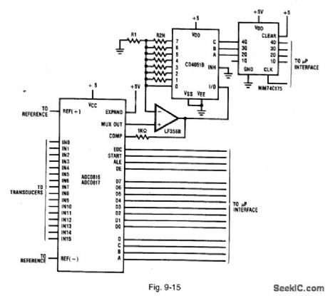
ADC_with_at_icroprocessor_con_trolled_gain
Published:2009/7/25 4:58:00 Author:Jessie | From:SeekIC

Figure 9-15 shows the ADC0816/17 connected for an external gain-control under supervision of a microprocessor. The CD4051 analog multiplexer is placed in the feedback loop of a simple noninverting op amp. The op-amp gain is controlled by selecting one of the CD4051 analog switches. This cuts a resistor in and out of the feedback loop. If the resistors (R2N) are of different value, different gains are realized. The gains are given by: Gain (AV) = 1 + (R2N/R1). A microprocessor (or some control logic) selects a gain by latching the channel address into a MM74C173. The LF356B output must not exceed the power supply. As a result, the op-amp gain must be reduced to a new level before a new channel is selected. The 1-kΩ resistor at the LF356B output helps protect the comparator inputs from accidental overvoltage (or undervoltage). The two back-biased diodes at the input to VCC and ground (1N914 or Schottky) offer further protection. NATIONAL SEMICONDUCTOR, APPLICATION NOTES 258, 1994, P. 602.
Reprinted Url Of This Article:
http://www.seekic.com/circuit_diagram/Basic_Circuit/ADC_with_at_icroprocessor_con_trolled_gain.html
Print this Page | Comments | Reading(3)

Article Categories
power supply circuit
Amplifier Circuit
Basic Circuit
LED and Light Circuit
Sensor Circuit
Signal Processing
Electrical Equipment Circuit
Control Circuit
Remote Control Circuit
A/D-D/A Converter Circuit
Audio Circuit
Measuring and Test Circuit
Communication Circuit
Computer-Related Circuit
555 Circuit
Automotive Circuit
Repairing Circuit
Code: