Basic Circuit
AC_BRIDGE
Published:2009/7/6 4:38:00 Author:May | From:SeekIC

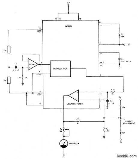
The circuit provides a simple and cost-effective solution to matching resistors and capacitors. Impedances ZR and Zx form a half-bridge, while OSC and OSC excite the bridge differentially. The external op amp is a FET input amplifier (LF356) with very low input bias current on the order of 30 pA (typical). C1 allows ac coupling by blocking the dc common mode voltage from the bridge, while RI biases the output of LF356 to 0 V at dc. Use of FET input op amp insures that dc offset due to bias current through R1 is negligible. Ac output of the demodulator is filtered via the uncommitted amp to provide dc voltage for the meter. The 10 k potentiometer, R5, limits the current into the meter to a safe level. Calibration begins by placing equal impedances at ZR and ZX, and the system offset is nulled by the offset adjust circuit so that Pin 1 is at 0 V. Next, known values are placed at Zx and the meter deviations are calibrated. The bridge is now ready to measure an unknown impedance at Zx with ±0.05% accuracy or better.
Reprinted Url Of This Article:
http://www.seekic.com/circuit_diagram/Basic_Circuit/AC_BRIDGE.html
Print this Page | Comments | Reading(3)

Article Categories
power supply circuit
Amplifier Circuit
Basic Circuit
LED and Light Circuit
Sensor Circuit
Signal Processing
Electrical Equipment Circuit
Control Circuit
Remote Control Circuit
A/D-D/A Converter Circuit
Audio Circuit
Measuring and Test Circuit
Communication Circuit
Computer-Related Circuit
555 Circuit
Automotive Circuit
Repairing Circuit
Code: