Basic Circuit
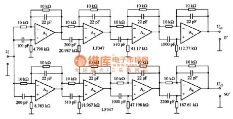
90°phase separation circuit
Published:2011/7/26 9:25:00 Author:Nancy | Keyword: phased separation | From:SeekIC

Figure 1 is the 90°phased separation circuit. It is a phase separation circuit formed by two circuits with the output phase difference keeping the same, it is used as a standby circuit of the variable frequency two phase oscillator or the basic signal source of the two phase lock-in amplifier. The circuit will offset 90 ° phase frequency into 8 sections, which are: f1=331.7KHz,f2=37.92KHz,f3=7.5799KHz,f4=1.4115kHz,f5=90.62kHz,f6=16.875KHz,f=3.372KHz,f=0.38561KHz.
Reprinted Url Of This Article:
http://www.seekic.com/circuit_diagram/Basic_Circuit/90°phase_separation_circuit.html
Print this Page | Comments | Reading(3)

Article Categories
power supply circuit
Amplifier Circuit
Basic Circuit
LED and Light Circuit
Sensor Circuit
Signal Processing
Electrical Equipment Circuit
Control Circuit
Remote Control Circuit
A/D-D/A Converter Circuit
Audio Circuit
Measuring and Test Circuit
Communication Circuit
Computer-Related Circuit
555 Circuit
Automotive Circuit
Repairing Circuit
Code: