Basic Circuit
8_BIT_BINARY_TO_DECIMAL_CONVERTER
Published:2009/7/12 22:37:00 Author:May | From:SeekIC

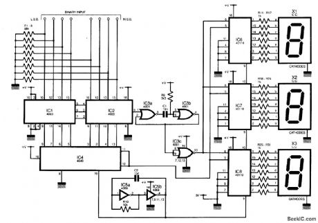
The decimal value of the eight input lines is displayed on three seven-segment displays. Although chips exist to perform this function for single displays, none include the possibility of displaying numbers greater than 9. No EPROM is necessary in this design. It operates by using two synchronized counters, one that generates an 8-bit binary output, and a second that drives the display. If the display is updated only when the binary counter is at the same value as the input, then the display will show the decimal value of the input. IC4 is the binary counter, and IC6 to IC8 form the display/counter section. IC5a and IC5b form the astable, which clocks both counters at 5 kHz.The minimum display refresh rate is, therefore, 20 times per second, IC1 and IC2 are two 4-bit comparators, ganged to form an 8-bit comparator. This compares the output of the binary counter (IC4) with the binary input taken from the circuit under test. Resistors RI to R8 pull down the input lines to prevent them from floating when no input is connected. When the comparator inputs are equal, pin 6 of IC2 goes high, triggering the monostable (IC3ab), which outputs a brief pulse. This latches the value of the display counters (IC6 to IC8) to the display. When IC4 reaches avalue of 256, the link between pins 11 and 12 resets the chip, and this resets the display counter also.
Reprinted Url Of This Article:
http://www.seekic.com/circuit_diagram/Basic_Circuit/8_BIT_BINARY_TO_DECIMAL_CONVERTER.html
Print this Page | Comments | Reading(3)

Article Categories
power supply circuit
Amplifier Circuit
Basic Circuit
LED and Light Circuit
Sensor Circuit
Signal Processing
Electrical Equipment Circuit
Control Circuit
Remote Control Circuit
A/D-D/A Converter Circuit
Audio Circuit
Measuring and Test Circuit
Communication Circuit
Computer-Related Circuit
555 Circuit
Automotive Circuit
Repairing Circuit
Code: