Basic Circuit
8080_interface_with_partial_decoding
Published:2009/7/25 5:06:00 Author:Jessie | From:SeekIC

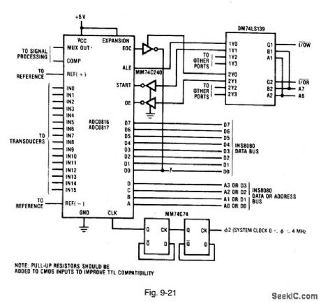
Figure 9-21 shows the ADC0816/17 connected with a DM74LS139 dual 2-4 decoder to form an 8080 interface with partial decoding. One half of the DM74SL139 is used to create read pulses, and the other half to create write pulses. The START and OE inputs are inverted to provide the correct pulse polarity. This interface partially decodes A6 and A7 to provide more I/O capabilities than the Fig. 9-20 circuit. The circuit in Fig. 9-21 also implements a simple polled-I/O structure. The EOC output is placed on the data bus by a tristate inverter when the inverter is enabled by a read pulse from the INS8080.
Reprinted Url Of This Article:
http://www.seekic.com/circuit_diagram/Basic_Circuit/8080_interface_with_partial_decoding.html
Print this Page | Comments | Reading(3)

Article Categories
power supply circuit
Amplifier Circuit
Basic Circuit
LED and Light Circuit
Sensor Circuit
Signal Processing
Electrical Equipment Circuit
Control Circuit
Remote Control Circuit
A/D-D/A Converter Circuit
Audio Circuit
Measuring and Test Circuit
Communication Circuit
Computer-Related Circuit
555 Circuit
Automotive Circuit
Repairing Circuit
Code: