Basic Circuit
650_MHz_AMPLIFYING_PRESCALER_PROBE
Published:2009/7/3 4:44:00 Author:May | From:SeekIC


CircU1t Notes
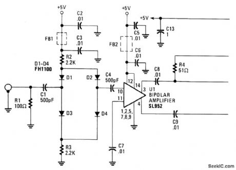
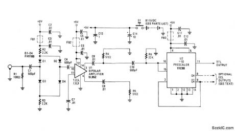
The 650 MHz Prescaler Probe's input is terminated by resistor R1 and is fed through C1 to the diode limiter composed of D1 through D4. Those diodes are forward-biased by the + 5 volt supply for small-input signals and, in turn, feed the signal to U1. Howev-er, for larger input signals, diodes Dl through D4 will start to turn off, passing less of the signal, and, thus, attenuating it. But even in a full-off state, the FH1100-type diodes will always pass a small part of the input to U1 because of capacitive leakage within the diodes. Integrated circU1t U1, a Plessey SL952 bipolar amplifier, capable of 1 GHz operation, provides 20 to 30 dB of gain. The input signal is supplied to pin 10, U1 withthe other input (pin 11) is bypassed to ground. The output signal is taken at pin 3 and pin 4, with pin 3 loaded by R4 and pin 4 by R5.Integrated circU1t 11C90, U2, is a high-speed prescaler capable of 650 MHz operation configured for a divide-by-10 format. A reference voltage internally generated appears at pin 15 and is tied to pin 16, the clock input. This centers the capacitive-coupled input voltage from U1 around the switching threshold-voltage level. An ECL-to-TTL converter in U1 provides level conversion to drive TTL input counters by typing pin 13 low.Therefore, no external EOL to TTL converter is reqU1red at the pin 11 output. On the other hand, EOL outputs are available at U2, pin 8 (Q4) and at pin 9 (Q4), if desired.In that circU1t configuration, pin 13 is left open, and U2 will use less power.
Reprinted Url Of This Article:
http://www.seekic.com/circuit_diagram/Basic_Circuit/650_MHz_AMPLIFYING_PRESCALER_PROBE.html
Print this Page | Comments | Reading(3)

Article Categories
power supply circuit
Amplifier Circuit
Basic Circuit
LED and Light Circuit
Sensor Circuit
Signal Processing
Electrical Equipment Circuit
Control Circuit
Remote Control Circuit
A/D-D/A Converter Circuit
Audio Circuit
Measuring and Test Circuit
Communication Circuit
Computer-Related Circuit
555 Circuit
Automotive Circuit
Repairing Circuit
Code: