Basic Circuit
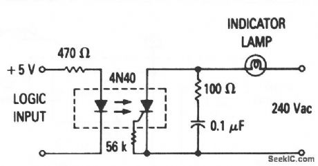
25_W_logic_indicator_lamp_driver
Published:2009/7/24 11:44:00 Author:Jessie | From:SeekIC

This circuit makes it possible to directly couple (without buffers) TTL and DTL inputs with either indicator or alarm devices. The optoelectronic coupling prevents both logic glitches and the introduction of noise. Motorola Thyristor Device Data, 1989, p. 6-20.
Reprinted Url Of This Article:
http://www.seekic.com/circuit_diagram/Basic_Circuit/25_W_logic_indicator_lamp_driver.html
Print this Page | Comments | Reading(3)

Article Categories
power supply circuit
Amplifier Circuit
Basic Circuit
LED and Light Circuit
Sensor Circuit
Signal Processing
Electrical Equipment Circuit
Control Circuit
Remote Control Circuit
A/D-D/A Converter Circuit
Audio Circuit
Measuring and Test Circuit
Communication Circuit
Computer-Related Circuit
555 Circuit
Automotive Circuit
Repairing Circuit
Code: