© 2008-2012 SeekIC.com Corp.All Rights Reserved.
Basic Circuit
10_dB_50_W_ATTENUATOR
Published:2009/7/12 22:54:00 Author:May | From:SeekIC

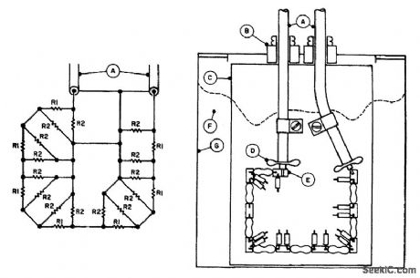
The 10-dB attenuator has an attenuation of 10 dB at lower frequencies at 2 m and 70 cm; circuit losses increase to 10.8 dB and 12.0 dB, including interconnecting RG-58/U cable losses of 0.4 dB and 0.6 dB, respectively. Establishing an SWR of less than 1.1:1 at 70 cm was the most crucial design consideration. Changes occur with different coolants. If the assembly is tailored for minimum SWR in air, its SWR increases to about 1.3:1 when you put it in vegetable oil. The SWR changes are caused by increased circuit capacitance due to the dielectric. This condition was improved by using household wax, paraffin, instead of oil. Cctution: Paraffin has ct relatively Lou;ftctsh temperature; it can be used to make candles. Next, to decrease the circuit distributed capacitance, increase the distance of the components from the circuit board by stacking two layers of PC boards at the tie-down pads.This raises the parts of connecting positions to about 0. 120 in. The completed assembly has an SWR of less than 1. 1 : 1 at both 70 cm and 2 m. Schematic and layout of the 10-dB attenuator: R1, 10-Ω 1/2-W (7); R2, 1-kΩ 1/4 W (14). A. Input/output, 3 ft RG-58/U. B. Cable bushing, 1/4 in. clearance hole. C. Component mounting board, 3 1/2 inX23/8 inX1/14, in PCB. D. Fan out end cable braid, twist into two segments, and solder to PCB with ntinimum lead lengths. E. Component tie-down pads (9), double thickness glass-epoxy PCB, 1/4inX1/8 inX1.8 in pieces cemented together and into position with clear household cement (Elmer's). F. Coolant, household wax (paraffin). Fill container with melted wax to 1/4 in from the top. To melt wax, insert the container in hot water (about 200°F). G. Container, one-pint can.
Reprinted Url Of This Article:
http://www.seekic.com/circuit_diagram/Basic_Circuit/10_dB_50_W_ATTENUATOR.html
Print this Page | Comments | Reading(3)

Article Categories
power supply circuit
Amplifier Circuit
Basic Circuit
LED and Light Circuit
Sensor Circuit
Signal Processing
Electrical Equipment Circuit
Control Circuit
Remote Control Circuit
A/D-D/A Converter Circuit
Audio Circuit
Measuring and Test Circuit
Communication Circuit
Computer-Related Circuit
555 Circuit
Automotive Circuit
Repairing Circuit
New published articles
Response in 12 hours

Code: