Automotive Circuit
The time accumulation circuit
Published:2011/6/22 6:40:00 Author:qqtang | Keyword: time accumulation | From:SeekIC

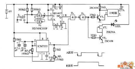
In the figure is the time accumulation circuit. In the circuit, H1 and H2 are vibrations generated by the switch, when the switch of S1 is pressed, it generates a passive pulse and triggers HD14027, and its 1-pin (Q terminal) outputs a high LEV, and the LEV is added on the input terminal of the timer by H3, H4 and VT1, then the timing is starting. ICM7555 composes the multi-resonance oscillator, by changing the RP2, the oscillating frequency is adjusted, the output pulse of the 3-pin of ICM7555 is also added on the input terminal of H3, then the timer begins to time the pulses. When the timing is over, press S1, which generates the passive pulse and triggers HD14027.
Reprinted Url Of This Article:
http://www.seekic.com/circuit_diagram/Automotive_Circuit/The_time_accumulation_circuit.html
Print this Page | Comments | Reading(3)

Article Categories
power supply circuit
Amplifier Circuit
Basic Circuit
LED and Light Circuit
Sensor Circuit
Signal Processing
Electrical Equipment Circuit
Control Circuit
Remote Control Circuit
A/D-D/A Converter Circuit
Audio Circuit
Measuring and Test Circuit
Communication Circuit
Computer-Related Circuit
555 Circuit
Automotive Circuit
Repairing Circuit
Code: