Automotive Circuit
The simple frequency multiplication generator
Published:2011/6/13 20:51:00 Author:Borg | Keyword: frequency multiplication generator | From:SeekIC


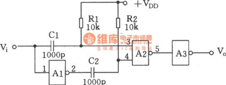
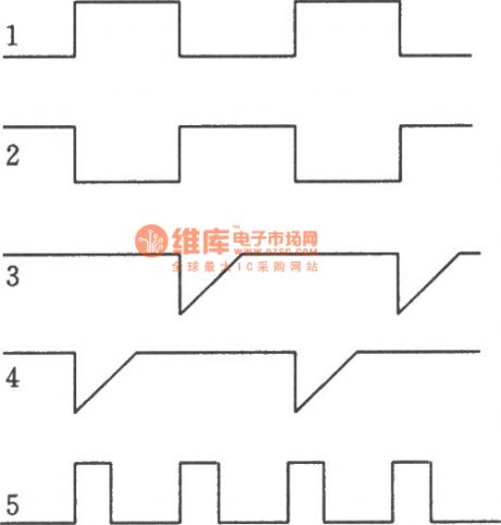
In the figure is the frequency multiplication circuit which consists of OR gates, the stepping-down edge of the input signal is differentiated by R1C1 and sent to the input terminal(3-pin) of A2, which makes A2 output a pulse, the stepping-up edge A1 is inverted and then it is sent to the input terminal(4-pin) of A2, so that A2 outputs a pulse again. As a result, by inputting a square wave, we can get two square waves at the output terminal of A2, and the frequency is doubled. A3 functions as the buffer and the rectifier. The wave outlines of the input signal are shown in the following figure.
Reprinted Url Of This Article:
http://www.seekic.com/circuit_diagram/Automotive_Circuit/The_simple_frequency_multiplication_generator.html
Print this Page | Comments | Reading(3)

Article Categories
power supply circuit
Amplifier Circuit
Basic Circuit
LED and Light Circuit
Sensor Circuit
Signal Processing
Electrical Equipment Circuit
Control Circuit
Remote Control Circuit
A/D-D/A Converter Circuit
Audio Circuit
Measuring and Test Circuit
Communication Circuit
Computer-Related Circuit
555 Circuit
Automotive Circuit
Repairing Circuit
Code: