Automotive Circuit
Storage Battery Voltage Monitor (1)
Published:2011/5/12 3:29:00 Author:Sue | Keyword: Storage, Battery, Voltage, Monitor | From:SeekIC
Working Principle:
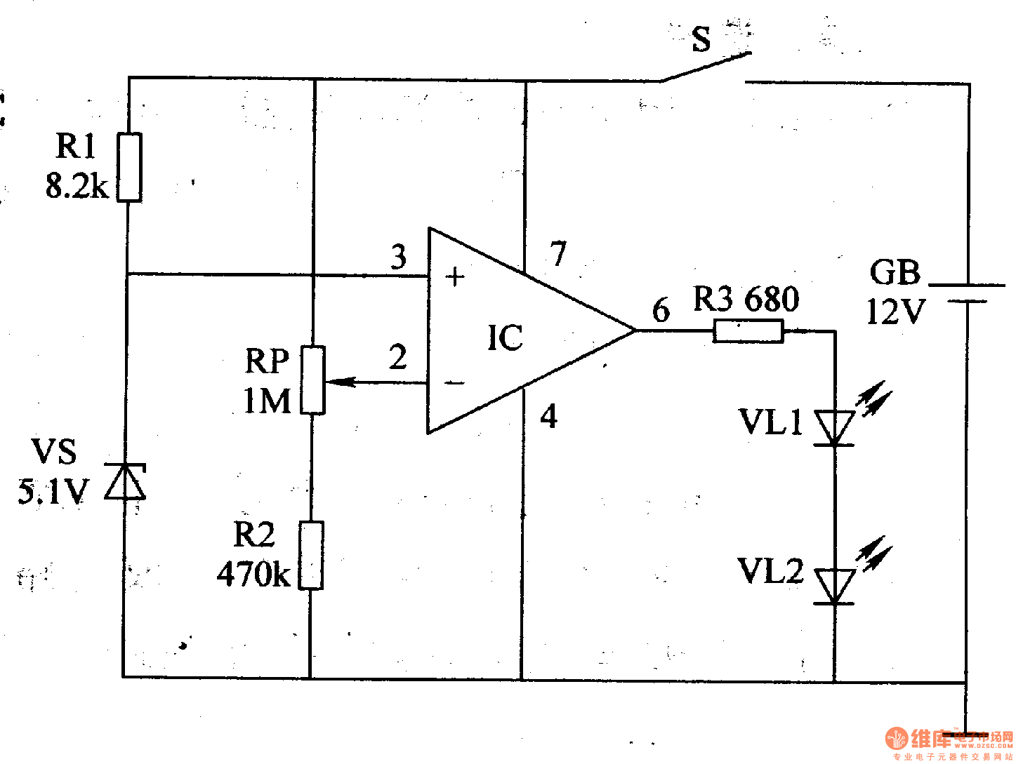
As seen in the figure 7-48, the storage battery voltage monitor circuit consists of operational amplifier integrated circuit IC, resistor R1-R3, potentiometer RP, zener diode VS, power switch S and LED VL1,VL2.
When S is connected, storage battery GB's +12V voltage provides IC's 3 pin with 5.1Vreference voltage after being limited and stablized by R and VS. While another voltage provides IC's 2 pin with sampling voltage after being divided by RP and R2.
When GB's terminal voltage exceeds 10.2V, IC outputshigh level because of 2 pin's voltage is higher than 3 pin's. So VL1 and VL2 are not illuminated.
When GB's terminal voltage doesn't reach 10.2V, IC outputslow level and VL1 VL2 are illuminated, indicating that battery voltage has reduced to preset threshold voltage, which means charging is needed.
Choice of components:
R1-R3: 1/4W metal film or carbon film resistor.
RP:Organic composition solid potentiometer or variable resistor.
VL1,VL2:φ5mm high-brightness red LED.
VS:1/2W,5.1V silicon voltage stablizing diode.
IC:μA741 integrated operational amplifier.
S: Miniture unipolar toggle swtich.
Reprinted Url Of This Article:
http://www.seekic.com/circuit_diagram/Automotive_Circuit/Storage_Battery_Voltage_Monitor_(1).html
Print this Page | Comments | Reading(3)

Article Categories
power supply circuit
Amplifier Circuit
Basic Circuit
LED and Light Circuit
Sensor Circuit
Signal Processing
Electrical Equipment Circuit
Control Circuit
Remote Control Circuit
A/D-D/A Converter Circuit
Audio Circuit
Measuring and Test Circuit
Communication Circuit
Computer-Related Circuit
555 Circuit
Automotive Circuit
Repairing Circuit
Code: